Honeywell CIPer 30 Installation Instructions Manual
Expansion io modules
Hide thumbs
Also See for CIPer 30:
- Installation instructions manual (7 pages) ,
- Installation and operation manual (41 pages)
Table of Contents
Advertisement
Quick Links
CIPer
TM
Introduction
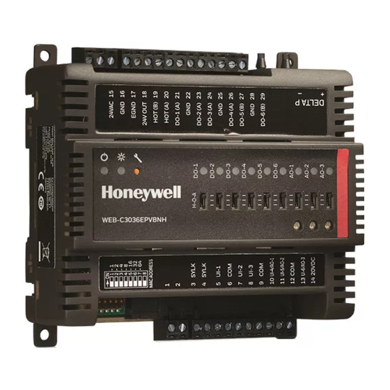
The CIPer Model 30 Expansion IO (EXPIO) are part of the CIPer family. The CIPer Model 30 programming model
allows user to connect extra input and output connections along with the on-board IO connections. The I/O points
which user can add externally as an expansion to existing on-board points are called as expansion I/O points.
The CIPer Model 30 Expansion IO (EXPIO) modules are available in two models as described in the table below:
Devices
WEB-O9056H
WEB-O3022H
Each device is programmable because the user chooses which function blocks to use and how to connect them. It
is configurable because each function block has user- defined behavior.
® U.S. Registered Trademark
Copyright © 2020 Honeywell Inc. ▪ All Rights Reserved
Model 30 Expansion IO Modules
UI
9
3
INSTALLATION INSTRUCTIONS
BO
6
2
UIO
5
2
31-00319-02
Advertisement
Table of Contents

Related Manuals for Honeywell CIPer 30


Summary of Contents for Honeywell CIPer 30
- Page 1 Each device is programmable because the user chooses which function blocks to use and how to connect them. It is configurable because each function block has user- defined behavior. ® U.S. Registered Trademark Copyright © 2020 Honeywell Inc. ▪ All Rights Reserved 31-00319-02...
-
Page 2: Specifications
Voltage rating 20-30 VAC, 50/60Hz Power consumption 100 VA for CIPer 30 EXPIO device and all connected loads. Note: Power consumption is based on the sum of the VA rating for each controller and should not exceed 100VA. If additional modules are required, then they must be powered from a separate transformer. -
Page 3: Dimension Drawings
The CIPer 30 EXPIO must be mounted in a position that allows clearance for wiring, servicing, removal, connection of the terminal blocks and access to the IP address and DIP switches. Both the CIPer 30 EXPIO (WEB-O9056H and WEB-O3022H) can be connected directly or remotely with CIPer Model 30 controller (WEB-C3036EPUBNH and WEB-C3036EPVBNH). - Page 4 Horizontally, with the connections on the top and bottom of the unit. The CIPer 30 EXPIO has a locking clip, similarly like CIPer Model 30 controller. Mounting on DIN rail ensures accu- rate alignment between all modules and controller. The CIPer 30 EXPIO can also be screw-mounted using the four mounting tabs, accessible under the covers.
- Page 5 CIPer MODEL 30 EXPANSION IO MODULES - INSTALLATION INSTRUCTIONS Figure 1: Stacked power wiring connection for CIPer Model 30 Controllers and EXPIO Remotely Mounting Figure 2: Remotely power wiring connection for CIPer Model 30 Controllers and EXPIO 31-00319-02...
- Page 6 CIPer MODEL 30 EXPANSION IO MODULES - INSTALLATION INSTRUCTIONS NOTE • The cable length is up to 40 meters max unterminated total length within the same building’s earth ground plane. • When you change the HOA switch to Off, Auto, and Hand mode in the physical device, there is a delay of one second.
-
Page 7: Terminal Blocks
Controller. Terminal Blocks The CIPer 30 Expansion IO uses removable terminal blocks to simplify field wiring of power and cabling. If desired, you can remove the terminal blocks from the unit, terminate cable, and reset the block when you finish. -
Page 8: Terminal Description
CIPer MODEL 30 EXPANSION IO MODULES - INSTALLATION INSTRUCTIONS Terminal Description WEB-O3022H Terminal Description 1, 3 Universal inputs UI-1 & UI-2 COM terminal for UI-1 & UI-2 Universal inputs UI-3 COM terminal for UI-3 Supplies 20V DC 24V AC output from controller for DO devices HOT (B) terminal. - Page 9 CIPer MODEL 30 EXPANSION IO MODULES - INSTALLATION INSTRUCTIONS WEB-O9056H Terminal Description 1, 3 Universal inputs, UI-1 & UI-2 COM terminal for UI-1 & UI-2 Universal inputs, UI-3 & UI-4 COM terminal for UI-3 & UI-4 Universal input, UI-5 COM terminal for UI-5 Supplies 20V DC 10, 12 Universal inputs, UI-6 &...
- Page 10 CIPer MODEL 30 EXPANSION IO MODULES - INSTALLATION INSTRUCTIONS 29, 31 Universal inputs UI-10/AO-1 & UI-11/AO-2 COM terminal for UI-10/AO-1 & UI-11/AO-2 32, 34 Universal inputs UI-12/AO-3 & UI-13/AO-4 COM terminal for UI-12/AO-3 & UI-13/AO-4 Universal inputs UI-14/AO-5 COM terminal for UI-14/AO-5 Wiring All wiring must comply with applicable electrical codes and ordinances, or as specified on installation wiring dia- grams.
- Page 11 CIPer MODEL 30 EXPANSION IO MODULES - INSTALLATION INSTRUCTIONS Each terminal can accommodate the following gauges of wire: − Single wire: 22 AWG to 14 AWG solid or stranded − Multiple wires: up to two 18 AWG stranded, with 1/4 watt wire-wound resistor NOTES •...
- Page 12 CIPer MODEL 30 EXPANSION IO MODULES - INSTALLATION INSTRUCTIONS NOTES • For multiple controllers and devices operating from a single transformer, the same side of the transformer secondary must be connected to the same power input terminal in each controller. Controller and device configurations will not necessarily be limited to three de- vices, but the total power draw, including accessories, cannot exceed 100 VA when pow- ered by the same transformer (U.S.
-
Page 13: Conformance Statement
This device complies with Part 15 of the FCC rules. Operation is subject to the following two conditions: (1) This device may not cause harmful interference, and (2) this device must accept any interference received, including interference that may cause undesired operation Honeywell Building Technologies Honeywell International Inc. ® U.S. Registered Trademark 1985 Douglas Drive North ©...
Need help?
Do you have a question about the CIPer 30 and is the answer not in the manual?
Questions and answers