Table of Contents
Advertisement
Quick Links
Axis 01914-001: D101-A XF P3807 - User Manual
Manufacturer: Axis Communications
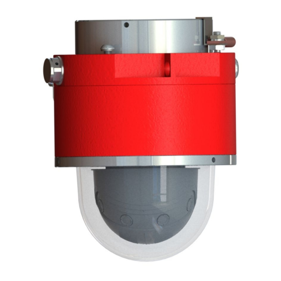
Product Type: Network Outdoor Dome Camera
Manufacturer Part Number: 01914-001
Model #: D101-A XF P3807
General Information
UPC: 7331021068865
•
UNSPSC: 46171610
•
Color Supported: Monochrome
•
Image Sensor Type: RGB CMOS
•
Effective Camera Resolution: 8 Megapixel
•
Maximum Video Resolution: 4320 x 1920
•
Related Links (Right click to open in new tab)
Visit the
01914-001 | D101-A XF P3807
View
over 1170 other Axis products
View list of all the
other manufacturers
# Require Multiple Quantities? Email us for Bulk Pricing
Scroll down to view the Axis 01914-001 | D101-A XF P3807 User Manual
product page for detailed information
we carry
Advertisement
Table of Contents

Related Manuals for Axis 01914-001


Summary of Contents for Axis 01914-001
- Page 1 View over 1170 other Axis products View list of all the other manufacturers we carry # Require Multiple Quantities? Email us for Bulk Pricing Scroll down to view the Axis 01914-001 | D101-A XF P3807 User Manual...
- Page 2 D101-(X)-P3807-BD Explosion Camera Proof Network Camera Installation Manual 105607312018 D101-(X)-P3807-PVE-BD INSTALLATION MANUAL REV-0...
- Page 3 Thispageintentionallyleftblank 105607312018 D101-(X)-P3807-PVE-BD INSTALLATION MANUAL REV-0...
- Page 4 Information in this document is subject to change without notice. All terms mentioned in this manual that are known to be trademarks have been appropriately capitalized. Spectrum Camera Solutions LLC acknowledges all trademark(s) and the rights of the trademark(s) owned by the company referred to herein.
- Page 5 Copyright Notice: This document contains information proprietary to Spectrum Camera Solutions LLC with all rights reserved worldwide. Any reproduction or disclosure of this publication, or any part thereof, to persons other than Spectrum Camera Solutions, Inc. personnel or customers is strictly prohibited, except by written permission of Spectrum Camera Solutions, Inc.
-
Page 6: Table Of Contents
Table of Contents Legal Notices and Revision History Inside front cover Page DESCRIPTION MODEL MATRIX LABELS STANDARDS AND CERTIFICATIONS DOCUMENT SYMBOLS HOW TO USE THIS MANUAL GENERAL SAFETY AND OPERATING INFORMATION 12-14 SPECIFICATIONS 15-17 INSTALLATION 18-24 DIMENTIONAL GENERAL ASSEMBLY HARDWARE BOM DISMANTLING &... -
Page 7: Description
DESCRIPTION The “D” Series includes a full range of Stainless Steel or Anodized Aluminum camera stations specifically designed for Hazardous Area Applications. Spectrum’s D Series is the first Class I Division 1 rated dome style explosion proof housings, and utilizes the most robust and advanced camera technologies available. The D Series was designed with the integrator in mind and offers features never before seen in current camera systems. -
Page 8: Model Matrix
*Internal components and D Series must be approved by Spectrum **Internal Equipment Manufacturer Code below ***Must be approved and verified by Spectrum ****Models supplied with Breather Drains will have IP66 ingress protection level CODE “XX” Manufacture AXIS COMMUNICATIONS 105607312018 D101-(X)-P3807- PVE-BD INSTALLATION MANUAL REV-0... -
Page 9: Labels
Labels BREATHER DRAIN MODEL BREATHER DRAIN MODEL 105607312018 D101-(X)-P3807- PVE-BD INSTALLATION MANUAL REV-0... -
Page 10: Standards And Certifications
STANDARDS & CERTIFICATIONS STANDARDS- The equipment is manufactured in accordance with the IECEX scheme, the ATEX Directive 2014/34/EU and with the following standards : IEC 60079-0:2011 IEC 60079-1:2014 IEC 60079-31:2013 IEC 60529:2013 EN 60079-0:2012 + A11:2013 EN 60079-1:2014 EN 60079-31:2014 EN 60529:1991 + A1:2000 + A2:2013 ANSI/ISA 60079-0:2013 ANSI/UL 60079-1:2015... -
Page 11: Document Symbols
DOCUMENT SYMBOLS The following symbols are used throughout this manual to alert users to potential hazards or important information. Failure to heed the warnings and cautions listed herein can lead to injury and equipment damage. Symbol Label Description Consists of conditions, practices, or procedures that WARNING: must be observed to prevent personal injury and/or equipment damage. -
Page 12: How To Use This Manual
How to use this Manual General Manual: This manual is intended to be used in conjunction with installed equipment manual from internal equipment manufacturer. Note: In the event of a conflict between the requirements of this general installation manual and the internal equipment manual, the safety and installation procedures described in this manual shall take precedence. -
Page 13: General Safety And Operating Information
General Safety and Operating Information: General safety and operating information applicable to electrical equipment installed within hazardous locations. This information must be understood by all persons installing, using, or maintaining the electrical equipment. This information is designed to aid personnel in safe installation, operation, and maintenance of the "D"... - Page 14 General Safety and Operating Information: Electrical Power: The "D" Series IP cameras operate from a variety of power options including IEEE compliant POE devices. • The power supply used with this product shall fulfill the requirements for Safety Extra Low Voltage (SELV) and Limited Power Source (LPS) according to IEC/EN/UL 62368-1 or IEC/EN/UL 60950-1 or Listed Class II Power Source Equipment.
- Page 15 General Safety and Operating Information: Installation: The installation must be realized in accordance with IEC/EN 60079-14 and/or in accordance with the national requirements. This equipment must be installed and used only by qualified personnel, having knowledge concerning electrical equipment for use in potentially explosive areas containing gas and/or dust.
-
Page 16: Specifications
SPECIFICATIONS CERTIFICATIONS of Model- D101-(X)-P3807-PVE-BD CERT NO. FM17US0156 & FM18CA0103X Class I Division 1 Groups B,C,D T6, Ta = -20°C to +55°C Type 4X, IP66 Class II/III, Division 1, Groups E,F,G T6 Type 4X, IP66/67 Ta = -20°C to +55°C Class I, Zone 1, AEx/Ex db IIB+H2 T6 Gb Ta = -20°C to +55°C, Type 4X, IP66 Zone 21, AEx/Ex tb IIIC T85°C Db Ta = -20°C to +55°C, Type 4X, IP66 CERT NO. - Page 17 D101-(X)-P3807-PVE-BD Explosion Proof Camera Hazardous Area Voltage Material Model Number 316L STAINLESS STEEL or D101-X-P3807-PVE-BD IEEE 802.3af/at Type 2 Class 4 ANODIZED ALUMINUM PoE Midspans/PoE Injectors Power Source Specification For D101-(X)-P3807-PVE- Reference Axis Manual 105607312018 D101-(X)-P3807- PVE-BD INSTALLATION MANUAL REV-0...
- Page 18 WIRING ENTRIES Conduit Entries are M20 x 1.5 Use appropriate Adapter With Nylon Washer or O-ring to keep ingress protection CAUTION: Ensure the Ethernet cable is disconnected from power source prior to wiring to the terminal block 105607312018 D101-(X)-P3807- PVE-BD INSTALLATION MANUAL REV-0...
-
Page 19: Installation
INSTALLATION Ensure that power is off before attempting to connect and wire the camera 1. Use supplied M6 Hex tool to unscrew bolts and lock washers supplied on camera Figure 1. wall bracket installation 2. Make sure threads on camera and M10x 1.5 are free of dirt and debris. Place mount on camera and align holes and tighten bolts 3. - Page 20 INSTALLATION 4. Use supplied M5 supplied Hex tool to loosen D1005 terminal cap by turning counterclockwise Figure 2. Removing D1005 terminal cap 5. Set D1005 terminal cap in safe place 6. Route cable(s) into D1006 terminal housing junction box through user-supplied cable gland and seal using the recommended gland installation practices.
- Page 21 INSTALLATION Figure 3. Conduit Entries are M20 x 1.5 Use appropriate Adapter With Nylon Washer or O-ring to keep ingress protection Example of CMP M20 to 3/4NPT adapter with Nylon Washer Figure 4. CAUTION: Ensure the Ethernet cable is disconnected from power source prior to wiring to the terminal block 105607312018 D101-(X)-P3807- PVE-BD INSTALLATION MANUAL...
- Page 22 INSTALLATION 7. Connect the wiring using installer supplied small screw driver to push the open terminal block contact. Insert wires and remove screw driver. Adhere to local electrical codes/laws. Table 1. Power Connection To "D" Series Camera TERMINAL NUMBER WIRE Position - 1 White-Orange Position - 2...
- Page 23 INSTALLATION 8. In addition to the internal ground connection, this equipment is also provided by an external secondary ground connection. Both must be connected for the internal ground the section must be equal to the active conductors. The external ground can receive a wire of 4 mm. The user/installer must connect the internal and external earthing before powering.
- Page 24 INSTALLATION 9. Ensure threads on D1005 terminal cap and D1006 Terminal housing are free of dirt and debris. 10. Ensure gasket is free of dirt and debris 11. Reinstall D1005 terminal cap using supplied M5 supplied Hex tool to tighten by turning clockwise until hand tight and gasket is seated Figure 7.
- Page 25 INSTALLATION 13. Remove Protective film after installation. If protective film is not removed in timely manor damage to dome is likely to occur with UV exposure 14. Apply power. For internal equipment startup procedures, setting changes, and troubleshooting guides reference the camera manufacturer’s manual included with the "D" Series Cameras. If the included copy is lost please contact support@spectrumcamera.com NOTE: Do not install camera unless power is applied in near future.
-
Page 26: Dimentional General Assembly
Dimensional General Assembly: 105607312018 D101-(X)-P3807- PVE-BD INSTALLATION MANUAL REV-0... -
Page 27: Hardware Bom
HARDWARE BOM 1- (QTY 1)EXTERNAL GROUND LUG 2- (QTY 3)M10 X 1.5 18-8 BOLT 3- (4 SETS) WEDGE LOCK WASHER 4- (QTY 1)D2005 Z-CLIP 5- SD-WM (WALL MNT. NOT INCLUDED) 6- M10X1.25 M10X1.5 ADAPTER 105607312018 D101-(X)-P3807- PVE-BD INSTALLATION MANUAL REV-0... -
Page 28: Dismantling & Maintenance
Lastly, apply coating of Repel (by Unelko corporation) surface cleaner. Never use harsh chemicals or abrasive towels. Replacing the battery- The Axis P3807-PVE product uses a *Panasonic 3.0 V BR2032 lithium battery Lithium primary battery composed of cathode from carbon monofluoride anode from lithium and electrolyte from organic solvent and lithium salt as the power supply for its internal real-time clock (RTC). -
Page 29: Mounting Options
SD-HM HORIZONTAL MOUNT 105607312018 D101-(X)-P3807- PVE-BD INSTALLATION MANUAL REV-0... - Page 30 SD-WM EXT WALL MOUNT 105607312018 D101-(X)-P3807- PVE-BD INSTALLATION MANUAL REV-0...
- Page 31 SD-PMA POLE MOUNT ADAPTER HARDWARE QTY 4 7/8-20 18-8 Bolts QTY 2 12in all thread with nuts and washers QTY 2 A1612 sides 105607312018 D101-(X)-P3807- PVE-BD INSTALLATION MANUAL REV-0...
- Page 32 SD-CM CORNER MOUNT HARDWARE- QTY 4 7/8-20 18-8 Bolts 105607312018 D101-(X)-P3807- PVE-BD INSTALLATION MANUAL REV-0...
- Page 33 SD-VM VIBRATION MOUNT HARDWARE- QTY 4 7/8-20 18-8 Bolts FRONT 105607312018 D101-(X)-P3807- PVE-BD INSTALLATION MANUAL REV-0...
- Page 34 SD-SO STANDOFF MOUNT HARDWARE- QTY 4 7/8-20 18-8 Bolts FRONT BACK 105607312018 D101-(X)-P3807- PVE-BD INSTALLATION MANUAL REV-0...
- Page 35 ASSEMBLY MOUNTS SD-CM+SD-VM+SD-SO+ SD-PMA SD-CM+SD-PMA 105607312018 D101-(X)-P3807- PVE-BD INSTALLATION MANUAL REV-0...
- Page 36 EU Declaration of Conformity Doc No. 100108292018 Spectrum Camera Solutions, 2014/34/EU Spectrum Camera Solutions declares that under our sole responsibility that the product (s) listed below conform to the relevant provisions of 2014/34/EU of August 29, 2018 Notified Body FM Approvals Ltd. 1 Windsor Dials, Windsor, Berkshire, UK.
- Page 37 Attestation of Conformity Doc No. 100108292018 Spectrum Camera Solutions, 2014/34/EU Spectrum Camera Solutions declares that under our sole responsibility that the product (s) listed below conform to the relevant provisions of 2014/34/EU of August 29, 2018 Notified Body FM Approvals Ltd. 1 Windsor Dials, Windsor, Berkshire, UK.
Need help?
Do you have a question about the 01914-001 and is the answer not in the manual?
Questions and answers