Panasonic AK-HRP1015G Operating Manual
Remote operation panel
Hide thumbs
Also See for AK-HRP1015G:
- Operating manual (44 pages) ,
- Operating manual (39 pages) ,
- Operating manual (37 pages)
Table of Contents
Advertisement
Quick Links
Operating Guide
Read this document when using the AK-HRP1015G Remote Operation Panel in
conjunction with AK-UB300G Series Multi-Purpose Cameras.
For details of operating Remote Operation Panel AK-HRP1015G, please
visit the Panasonic website (https://pro-av.panasonic.net/manual/en/index.
html), and refer to the Operating Instructions (HTML or PDF).
W0321AM0 -PS
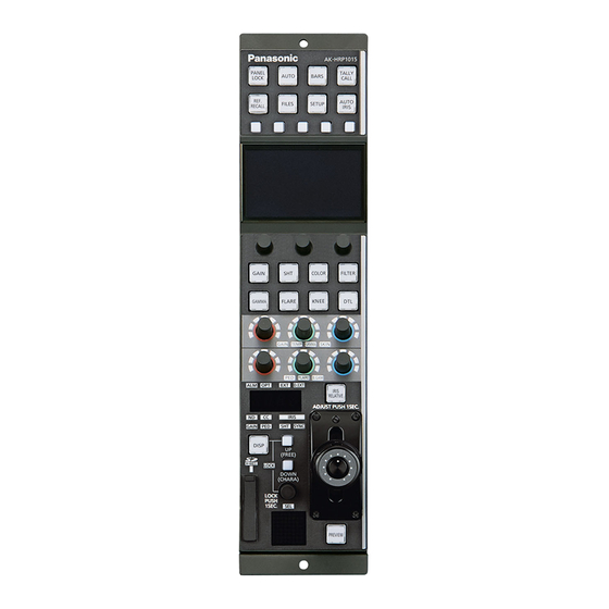
Remote Operation Panel
AK-HRP1015G
Model No.
ENGLISH
DVQP2521ZA
Advertisement
Table of Contents

Related Manuals for Panasonic AK-HRP1015G


Summary of Contents for Panasonic AK-HRP1015G
- Page 1 Operating Guide Remote Operation Panel AK-HRP1015G Model No. Read this document when using the AK-HRP1015G Remote Operation Panel in conjunction with AK-UB300G Series Multi-Purpose Cameras. For details of operating Remote Operation Panel AK-HRP1015G, please visit the Panasonic website (https://pro-av.panasonic.net/manual/en/index.
-
Page 2: Table Of Contents
Table of Contents Connecting the Unit to AK-UB300G Series Cameras System block diagram Connections Compatible Functions List ROP Menu (when AK-UB300G is connected) ROP menu list 01 PAINT SWITCH 02 SCENE 03 SHUTTER SPEED 04 FILTER 05 PEDESTAL 06 CHROMA 07 RB GAIN 08 COLOR TEMP 09 FLARE... -
Page 3: Connecting The Unit To Ak-Ub300G Series Cameras
For HD main line: Use the output from the <HD SDI OUT 1> terminal, or the output from the <UHD/HD SDI OUT 1>/<UHD/HD SDI OUT 2> terminal. For HD monitor: Use the output from the <HD SDI OUT 2> terminal. Remote operation panel Connect AK-HRP1015G to the <I/F> terminal or the <LAN> terminal of the AK-UB300G. - 3 -... -
Page 4: Connections
Connecting the Unit to AK-UB300G Series Cameras Connections Set the connection setting to [Serial(AW)] or [LAN(AW)] in the [CONNECT SETTING] menu. When connecting, observe the following points. Serial connection Use a dedicated cable to connect the [CCU] connector of this unit to the <I/F> terminal of the AK-UB300G. Use a PoE injector for the power supply. -
Page 5: Compatible Functions List
Connecting the Unit to AK-UB300G Series Cameras Compatible Functions List When the unit is used in conjunction with an AK-UB300G Series Multi-Purpose Camera, some of the unit's button, dial, and other control functions will be limited or disabled. Be sure to refer to the following table. NOTE The descriptions in this document assume that the system version of the unit is V2.00-00-0.00 or later. - Page 6 Connecting the Unit to AK-UB300G Series Cameras ✓: Enabled Number Part name Remarks ×: Disabled ✓ [GAIN] button When this is set to ON, the white balance menu appears on the LCD panel. ✓ [SHT] button When this is set to ON, the shutter menu appears on the LCD panel.
- Page 7 Connecting the Unit to AK-UB300G Series Cameras ✓: Enabled Number Part name Remarks ×: Disabled ✓ [ALM] indicator [OPT] indicator × [EXT] indicator × [D.EXT] indicator × ✓ Adjustment value display The adjustment value of the CC filter is not displayed.
-
Page 8: Rop Menu (When Ak-Ub300G Is Connected)
ROP Menu (when AK-UB300G is connected) ROP Menu (when AK-UB300G is connected) ROP menu list When an AK-UB300G Multi-Purpose Camera is connected, the ROP menu will be as follows. NOTE The descriptions in this document assume that the system version of the unit is V2.00-00-0.00 or later. Make sure that the system version of the AK-UB300G used in conjunction with the unit is V7.52-000-00.00 or later. - Page 9 ROP Menu (when AK-UB300G is connected) “FLARE R” (see page 22) FLARE R FLARE G “FLARE G” (see page 22) 09 FLARE FLARE B “FLARE B” (see page 22) M.FLARE “M.FLARE” (see page 22) “FLARE” (see page 22) FLARE “GAMMA R” (see page 23) GAMMA R “GAMMA MASTER”...
- Page 10 ROP Menu (when AK-UB300G is connected) “MEMORY SELECT” (see page 28) MEMORY SELECT CURSOR “CURSOR” (see page 28) POS H “POS H” (see page 28) POS V “POS V” (see page 28) “SKIN GET” (see page 28) SKIN GET “ZEBRA SWITCH” (see page 28) ZEBRA SWITCH “ZEBRA EFFECT”...
- Page 11 ROP Menu (when AK-UB300G is connected) “LINEAR TABLE” (see page 33) LINEAR TABLE COLOR CORRECT “COLOR CORRECT” (see page 33) COLOR CORRECT “COLOR CORRECT” (see page 33) “SAT” (see page 33) “PHASE” (see page 33) PHASE “SAT G” (see page 33) SAT G “PHASE G”...
- Page 12 ROP Menu (when AK-UB300G is connected) “FORMAT” (see page 39) FORMAT CROP OUT “CROP OUT” (see page 39) CROP MARKER “CROP MARKER” (see page 39) CROP ADJ “CROP ADJ” (see page 39) “CROP H POS (%)” (see page 39) CROP H POS (%) 21 SYSTEM CAM “CROP V POS (%)”...
- Page 13 ROP Menu (when AK-UB300G is connected) IP ADDRESS 1 Refer to the following section in the operating instructions. “39 ROP IP SETTING” IP ADDRESS 2 IP ADDRESS 3 IP ADDRESS 4 IP ADDRESS PORT IP ADDRESS UPLOAD SUBNET MASK 1 25 ROP IP SETTING SUBNET MASK 2 SUBNET MASK 3...
-
Page 14: Paint Switch
ROP Menu (when AK-UB300G is connected) 01 PAINT SWITCH Item Setting details MATRIX Enables/disables the matrix (linear matrix / 12-axis color correction). LINEAR MATRIX Enables/disables linear matrix. COLOR CORRECT Enables/disables 12-axis color correction. SKIN DTL Enables/disables the skin tone detail function. Enables/disables the detail. -
Page 15: Scene
ROP Menu (when AK-UB300G is connected) 02 SCENE Item Setting details SCENE1(push) Set the scene file to ON/OFF. When a scene file is set to ON, the other scene files will be set to OFF. SCENE2(push) If you reselect a scene file that is set to ON, it will be set to SCENE OFF. SCENE3(push) SCENE4(push) SCENE5(push) -
Page 16: Shutter Speed
ROP Menu (when AK-UB300G is connected) 03 SHUTTER SPEED Item Setting details SHUTTER SPEED Sets the shutter speed for when [SHUTTER MODE] is set to [SHUT]. SHUTTER SYNCHRO The setting cannot be set. SHUTTER SW Enables/disables the shutter function. SHUTTER MODE Selects the operation mode of the shutter. -
Page 17: Filter
ROP Menu (when AK-UB300G is connected) 04 FILTER Item Setting details Sets the ND filter position. - 17 -... -
Page 18: Pedestal
ROP Menu (when AK-UB300G is connected) 05 PEDESTAL Item Setting details PED R Sets the correction level of red to the master pedestal. PED B Sets the correction level of blue to the master pedestal. M. PED Adjusts the black level of the master pedestal. - 18 -... -
Page 19: Chroma
ROP Menu (when AK-UB300G is connected) 06 CHROMA Item Setting details CHROMA LEVEL Adjusts the chroma gain when [CHROMA SW] is set to [ON]. CHROMA LEVEL SW Enables/disables the gain adjustment of chroma. - 19 -... -
Page 20: Rb Gain
ROP Menu (when AK-UB300G is connected) 07 RB GAIN Item Setting details GAIN AWB R Sets the correction level of red to the gain. GAIN AWB B Sets the correction level of blue to the gain. - 20 -...
Need help?
Do you have a question about the AK-HRP1015G and is the answer not in the manual?
Questions and answers