Panasonic AK-HRP1015G Operating Manual
Remote operation panel
Hide thumbs
Also See for AK-HRP1015G:
- Operating manual (44 pages) ,
- Operating manual (20 pages) ,
- Operating manual (32 pages)
Table of Contents
Advertisement
Operating Guide
Read this document when using the AK-HRP1015G Remote Operation Panel in
conjunction with AW-HR140 or AW-HE130 Series HD Integrated Cameras.
For details of operating Remote Operation Panel AK-HRP1015G, please
visit the Panasonic website (https://pro-av.panasonic.net/manual/en/index.
html), and refer to the Operating Instructions (HTML or PDF).
W0321AM0 -PS
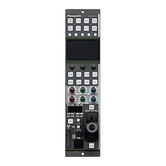
Remote Operation Panel
AK-HRP1015G
Model No.
ENGLISH
DVQP2526ZA
Advertisement
Table of Contents

Related Manuals for Panasonic AK-HRP1015G


Summary of Contents for Panasonic AK-HRP1015G
- Page 1 Remote Operation Panel AK-HRP1015G Model No. Read this document when using the AK-HRP1015G Remote Operation Panel in conjunction with AW-HR140 or AW-HE130 Series HD Integrated Cameras. For details of operating Remote Operation Panel AK-HRP1015G, please visit the Panasonic website (https://pro-av.panasonic.net/manual/en/index.
-
Page 2: Table Of Contents
Table of Contents Connecting the Unit to AW-HR140/AW-HE130 Series Cameras Connection examples Connections Compatible Functions List ROP Menu (when AW-HR140/AW-HE130 is connected) ROP menu list 01 SCENE 02 SHUTTER SPEED 03 FILTER 04 PEDESTAL 05 CHROMA 06 GAIN 07 WHITE BALANCE 08 GAMMA 09 KNEE 10 WHITE CLIP... -
Page 3: Connecting The Unit To Aw-Hr140/Aw-He130 Series Cameras
Connecting the Unit to AW-HR140/AW-HE130 Series Cameras Connecting the Unit to AW-HR140/AW-HE130 Series Cameras Connection examples Serial connection with AW-HR140 IP connection with AW-HR140 HD Integrated Camera HD Integrated Camera AW-HR140 AW-HR140 External DC External DC power supply power supply <RS-422>... - Page 4 PoE compatible switching hub or injector Switching hub with PoE support LAN cable (straight cable) Serial connection cable specifications AK-HRP1015G [CCU] connector side AW-HR140/AW-HE130 Pin No. Function Polarity Flow of signal <RS-422> connector side (RJ45)
-
Page 5: Connections
Connecting the Unit to AW-HR140/AW-HE130 Series Cameras Connections Set the connection setting to [Serial(AW2)] or [LAN(AW2)] in the [CONNECT SETTING] menu. NOTE To connect with the AW-HR140/AW-HE130, upgrade the system version of the unit to 2.00-00-0.00 or later. When connecting, observe the following points. Serial connection Use a dedicated cable to connect the [CCU] connector of this unit to the <RS-422>... -
Page 6: Compatible Functions List
Connecting the Unit to AW-HR140/AW-HE130 Series Cameras Compatible Functions List When the unit is used in conjunction with an AW-HR140 Series or AW-HE130 Series HD Integrated Camera, there will be functions that are limited or disabled for some of the unit’s buttons, dials, and other controls. Be sure to refer to the following table. Front panel 1 Front panel 2 Front panel 3... - Page 7 Connecting the Unit to AW-HR140/AW-HE130 Series Cameras ✓: Enabled Number Part name Remarks ×: Disabled ✓ [GAIN] button When this button is pressed, the gain menu appears on the LCD panel. The button is lit during menu display. ✓ [SHT] button When this button is pressed, the shutter menu appears on the LCD panel.
- Page 8 Connecting the Unit to AW-HR140/AW-HE130 Series Cameras ✓: Enabled Number Part name Remarks ×: Disabled ✓ [ALM] indicator [OPT] indicator × [EXT] indicator × ✓ [D.EXT] indicator ✓ Adjustment value display A value is also not displayed when [SHUTTER] is [SYNC]. The display will be bar display.
-
Page 9: Rop Menu (When Aw-Hr140/Aw-He130 Is Connected)
ROP Menu (when AW-HR140/AW-HE130 is connected) ROP Menu (when AW-HR140/AW-HE130 is connected) ROP menu list When an AW-HR140/AW-HE130 HD Integrated Camera is connected, the ROP menu will be as follows. For details on menu operations, refer to the following sections in the Operating Instructions. “Displaying menus”... - Page 10 ROP Menu (when AW-HR140/AW-HE130 is connected) “TYPE” (see page 25) TYPE “R-G” (see page 25) “R-B” (see page 25) 12 MATRIX “G-R” (see page 25) “G-B” (see page 25) “B-R” (see page 25) “B-G” (see page 25) “TYPE” (see page 27) TYPE COLOR CORRECT “COLOR CORRECT”...
- Page 11 ROP Menu (when AW-HR140/AW-HE130 is connected) “FAN” (see page 31) HEATER “HEATER” (see page 31) 16 HOUSING DFRSTR “DFRSTR” (see page 31) WIPER “WIPER” (see page 31) “WASHER(push)” (see page 31) WASHER(push) “PICTURE LEVEL” (see page 32) PICTURE LEVEL “FRAME MIX” (see page 32) 17 BRIGHTNESS FRAME MIX “DAY/NIGHT”...
- Page 12 ROP Menu (when AW-HR140/AW-HE130 is connected) IRIS LEV MOD Refer to the following section in the Operating Instructions. “37 ROP SETTING” M.PED CONTROL LOCK SELECT AUTO BUTTON G/M PED VOL FREE+LOCK CAMERA SELECT DTL BUTTON SKIN VOL LCD BRIGHT PANEL BRIGHT BUZZER PERIOD CYCLE...
- Page 13 ROP Menu (when AW-HR140/AW-HE130 is connected) ROP IP ADDRESS 1 Refer to the following section in the Operating Instructions. “39 ROP IP SETTING” ROP IP ADDRESS 2 ROP IP ADDRESS 3 ROP IP ADDRESS 4 PORT UPLOAD ROP SUBNET MASK 1 ROP SUBNET MASK 2 24 ROP IP SETTING ROP SUBNET MASK 3...
-
Page 14: Scene
ROP Menu (when AW-HR140/AW-HE130 is connected) 01 SCENE Item Setting details SCENE1(push) Switches the scene file. Switches to the scene set to ON. SCENE2(push) SCENE3(push) SCENE4(push) - 14 -... -
Page 15: Shutter Speed
ROP Menu (when AW-HR140/AW-HE130 is connected) 02 SHUTTER SPEED Item Setting details MODE Selects the operation mode of the shutter. SPEED Sets the shutter speed. The setting can be changed when [MODE] is [STEP]. The shutter speed of [SYNC] is not displayed. - 15 -... -
Page 16: Filter
ROP Menu (when AW-HR140/AW-HE130 is connected) 03 FILTER Item Setting details Sets the ND filter position. - 16 -... -
Page 17: Pedestal
ROP Menu (when AW-HR140/AW-HE130 is connected) 04 PEDESTAL Item Setting details M.PED Adjusts the black level of the master pedestal. PED R Sets the correction level of red to the master pedestal. PED B Sets the correction level of blue to the master pedestal. - 17 -... -
Page 18: Chroma
ROP Menu (when AW-HR140/AW-HE130 is connected) 05 CHROMA Item Setting details LEVEL(%) Sets the color intensity of images. - 18 -... -
Page 19: Gain
ROP Menu (when AW-HR140/AW-HE130 is connected) 06 GAIN [SUPER GAIN] is a function for only the AW-HR140. Item Setting details SUPER GAIN Enables/disables the super gain (increased sensitivity) function. GAIN Adjusts the gain of images. AGC MAX GAIN When [AUTO] is selected as the [GAIN] setting, the maximum gain-up amount can be set. - 19 -... -
Page 20: White Balance
ROP Menu (when AW-HR140/AW-HE130 is connected) 07 WHITE BALANCE [ATW SPEED] and [ATW WIDTH] are functions for only the AW-HR140. Item Setting details MODE Sets the white balance mode. COLOR TEMP Sets color temperature settings. GAIN R Adjusts the R gain. GAIN B Adjusts the B gain. -
Page 21: Gamma
ROP Menu (when AW-HR140/AW-HE130 is connected) 08 GAMMA Item Setting details TYPE Selects the type of gamma curve. GAMMA Adjusts the gamma correction level. Sets the DRS function which performs correction when video with high light/dark contrast is displayed. - 21 -... -
Page 22: Knee
ROP Menu (when AW-HR140/AW-HE130 is connected) 09 KNEE Item Setting details KNEE MODE Sets the operating mode for gradation compression (knee). KNEE POINT Sets the compression level (knee point) position for high-brightness video signals. KNEE SLOPE Sets the knee slope. - 22 -... -
Page 23: White Clip
ROP Menu (when AW-HR140/AW-HE130 is connected) 10 WHITE CLIP Item Setting details WHITE CLIP Enables/disables the white clip function. WHITE CLP LV(%) Sets the white clip level. - 23 -... -
Page 24: Detail
ROP Menu (when AW-HR140/AW-HE130 is connected) 11 DETAIL Item Setting details M.DTL Adjusts the level of master detail. V DTL LEVEL Adjusts the level of vertical detail. DTL BAND Sets the boost frequency for detail. NOISE SUPPRESS Reduces the screen noise which is generated by the detail effect. FLSHTN NIS SUP. -
Page 25: Matrix
ROP Menu (when AW-HR140/AW-HE130 is connected) 12 MATRIX Item Setting details TYPE Selects the type of color matrix. Adjusts the linear matrix between red and green. Adjusts the linear matrix between red and blue. Adjusts the linear matrix between green and red. Adjusts the linear matrix between green and blue. -
Page 26: Color Correction
ROP Menu (when AW-HR140/AW-HE130 is connected) 13 COLOR CORRECTION - 26 -... - Page 27 ROP Menu (when AW-HR140/AW-HE130 is connected) Item Setting details TYPE Selects the type of color matrix. COLOR CORRECT Selects the color component in 12-axis matrix memory to adjust. Adjusts the saturation of the color component selected in [COLOR CORRECT]. PHASE Adjusts the hue of the color component selected in [COLOR CORRECT].
- Page 28 ROP Menu (when AW-HR140/AW-HE130 is connected) Item Setting details SAT R Adjusts red color saturation. PHASE R Adjusts red hue. SAT R_R_Yl Adjusts the color saturation with a 3:1 red to yellow ratio. PHASE R_R_Yl Adjusts the hue (color phase) with a 3:1 red to yellow ratio. SAT R_Yl Adjusts the color saturation between red and yellow.
-
Page 29: Dnr
ROP Menu (when AW-HR140/AW-HE130 is connected) 14 DNR Item Setting details Sets the level for the noise reduction. - 29 -... -
Page 30: Digtal Haze Clear
ROP Menu (when AW-HR140/AW-HE130 is connected) 15 DIGTAL HAZE CLEAR Item Setting details LEVEL Sets the level of the haze elimination. The larger the value, the stronger the haze elimination effect. Enables/disables the haze elimination function. - 30 -... -
Page 31: Housing
ROP Menu (when AW-HR140/AW-HE130 is connected) 16 HOUSING Operation is possible only for the AW-HR140. Item Setting details Sets the cooling fan operation. HEATER Sets the heater operation. DFRSTR Sets the defroster device operation. WIPER Sets the wiper operation. WASHER(push) Clean the lens by spraying washer fluid on to it. -
Page 32: Brightness
ROP Menu (when AW-HR140/AW-HE130 is connected) 17 BRIGHTNESS Item Setting details PICTURE LEVEL Sets the target picture level for auto exposure correction. FRAME MIX Selects for frame addition (gain-up using sensor storage) amount. DAY/NIGHT Switches between standard shooting (day mode) and night-vision shooting (night mode: shooting with infrared light). -
Page 33: Lens Control
ROP Menu (when AW-HR140/AW-HE130 is connected) 18 LENS CONTROL Item Setting details FOCUS MODE Selects auto or manual mode for the focus adjustment function. FOCUS SPEED Adjusts the focus operation speed. FOCUS Adjusts the lens focus manually. ZOOM WIDE Adjusts the lens zoom to wide angle (Wide). ZOOM SPEED Adjusts the zoom operation speed. -
Page 34: Iris Relative
ROP Menu (when AW-HR140/AW-HE130 is connected) 19 IRIS RELATIVE For details on operations and settings, refer to the following sections in the Operating Instructions. “29 IRIS RELATIVE” - 34 -... -
Page 35: System Cam
ROP Menu (when AW-HR140/AW-HE130 is connected) 20 SYSTEM CAM [FREQUENCY], [3G SDI OUT], and [I.S.] are functions for only the AW-HR140. Item Setting details FORMAT Displays the system format. FREQUENCY Displays the frame frequency. 3G SDI OUT When the video format is 1080/59.94p or 1080/50p, select the format for outputting 3G-SDI signals. I.S. -
Page 36: Camera Menu Control
ROP Menu (when AW-HR140/AW-HE130 is connected) 21 CAMERA MENU CONTROL Item Setting details MENU ON/OFF Turns the menu on or off. CURSOR/PARAMETER Moves the menu cursor or changes setting values. EXECUTE Executes the selected process. - 36 -... -
Page 37: Rop Setting
ROP Menu (when AW-HR140/AW-HE130 is connected) 22 ROP SETTING For details on operations and settings, refer to the following sections in the Operating Instructions. “37 ROP SETTING” - 37 -... -
Page 38: Connect Setting
ROP Menu (when AW-HR140/AW-HE130 is connected) 23 CONNECT SETTING Item Setting details CONNECT MODE(push) CAM1 Sets the connection method for camera 1. Changes to settings are applied by pressing the [MENU] dial. Select [LAN(AW2)] and [Serial(AW2)] when connecting with the AW-HR140 series and AW-HE130 series. -
Page 39: Rop Ip Setting
ROP Menu (when AW-HR140/AW-HE130 is connected) 24 ROP IP SETTING For details on operations and settings, refer to the following sections in the Operating Instructions. “39 ROP IP SETTING” 25 CAMERA IP SETTING For details on operations and settings, refer to the following sections in the Operating Instructions. “40 CAMERA IP SETTING”...
Need help?
Do you have a question about the AK-HRP1015G and is the answer not in the manual?
Questions and answers