Panasonic AK-HRP1015G Operating Manual
Remote operation panel
Hide thumbs
Also See for AK-HRP1015G:
- Operating manual (44 pages) ,
- Operating manual (20 pages) ,
- Operating manual (32 pages)
Table of Contents
Advertisement
Quick Links
Operating Guide
Read this document when using the AK-HRP1015G Remote Operation Panel in
conjunction with AJ-CX4000G Memory Card Camera-Recorder.
For details of operating Remote Operation Panel AK-HRP1015G, please
visit the Panasonic website (https://pro-av.panasonic.net/manual/en/index.
html), and refer to the Operating Instructions (HTML or PDF).
W0321AM0 -PS
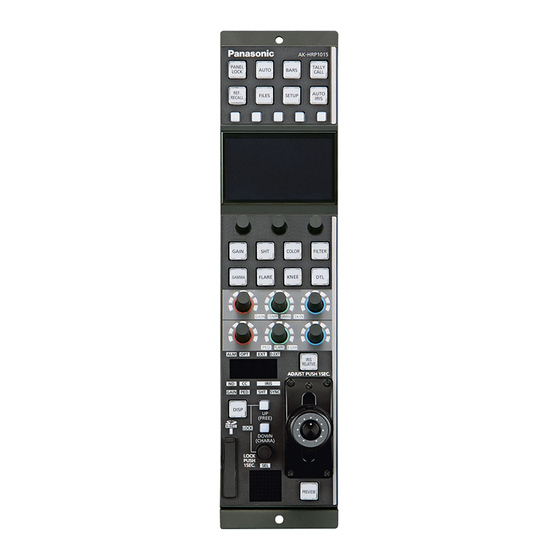
Remote Operation Panel
AK-HRP1015G
Model No.
ENGLISH
DVQP2546ZA
Advertisement
Table of Contents

Related Manuals for Panasonic AK-HRP1015G


Summary of Contents for Panasonic AK-HRP1015G
- Page 1 Operating Guide Remote Operation Panel AK-HRP1015G Model No. Read this document when using the AK-HRP1015G Remote Operation Panel in conjunction with AJ-CX4000G Memory Card Camera-Recorder. For details of operating Remote Operation Panel AK-HRP1015G, please visit the Panasonic website (https://pro-av.panasonic.net/manual/en/index.
-
Page 2: Table Of Contents
Table of Contents Connecting the Unit to AJ-CX4000 Cameras Connections Compatible Functions List ROP Menu (during AJ-CX4000 Connection) ROP menu list 01 SCENE 02 SHUTTER SPEED 03 FILTER 04 PEDESTAL 05 CHROMA 06 GAIN 07 COLOR TEMP 08 WHITE BALANCE 09 FLARE 10 GAMMA 11 KNEE... -
Page 3: Connecting The Unit To Aj-Cx4000 Cameras
Connecting the Unit to AJ-CX4000 Cameras Connecting the Unit to AJ-CX4000 Cameras Connections Use a LAN cable to connect the <REMOTE> connector at the rear of the AJ-CX4000 to the <LAN> connector of the AK- HRP1015G. Set the connection setting to “LAN(AJ2)” in the [CONNECT SETTING] menu. - 3 -... -
Page 4: Compatible Functions List
Connecting the Unit to AJ-CX4000 Cameras Compatible Functions List When the unit is used in conjunction with an AJ-CX4000 Memory Card Camera-Recorder, a portion of the unit’s button, dial, and other con- trol functions will be limited or disabled. Be sure to refer to the following table. Front panel 1 Front panel 2 Front panel 3... - Page 5 Connecting the Unit to AJ-CX4000 Cameras ✓: Enabled Number Part name Remarks ×: Disabled ✓ [GAIN] button When this is set to ON, the [GAIN] menu is dis- played on the LCD panel. ✓ [SHT] button When this is set to ON, the [SHUTTER SPEED] menu is displayed on the LCD panel.
- Page 6 Connecting the Unit to AJ-CX4000 Cameras ✓: Enabled Number Part name Remarks ×: Disabled ✓ [GAIN], [TEMP], [GAMMA], [SKIN] When [GAIN] is lit adjustment block Adjusts the following. Red (R) adjustment dial [WHITE BALANCE] > [GAIN R] Blue (B) adjustment dial [WHITE BALANCE] >...
- Page 7 Connecting the Unit to AJ-CX4000 Cameras ✓: Enabled Number Part name Remarks ×: Disabled ✓ [ALM] indicator [OPT] indicator × [EXT] indicator × [D.EXT] indicator × ✓ Adjustment value display Displays the adjustment values except for CC. When the [SHT] indicator and [SYNC] indicator are lit Displays the following.
-
Page 8: Rop Menu (During Aj-Cx4000 Connection)
ROP Menu (during AJ-CX4000 Connection) ROP Menu (during AJ-CX4000 Connection) ROP menu list When an AJ-CX4000 Memory Card Camera-Recorder is connected, the ROP menu will be as follows. For setting values related to the cam- era, refer to the Operating Instructions for the camera. For details on menu operations, refer to the following sections in the Operating Instructions. - Page 9 ROP Menu (during AJ-CX4000 Connection) “FLARE R” (see page 21) FLARE R FLARE G “FLARE G” (see page 21) 09 FLARE FLARE B “FLARE B” (see page 21) “SW” (see page 21) “MODE” (see page 22) MODE “GAMMA” (see page 22) GAMMA “SW”...
- Page 10 ROP Menu (during AJ-CX4000 Connection) “TABLE” (see page 28) TABLE ADAPTIVE MATRIX “ADAPTIVE MATRIX” (see page 28) “R-G” (see page 28) “R-B” (see page 28) 16 MATRIX “G-R” (see page 28) “G-B” (see page 28) “B-R” (see page 28) “B-G” (see page 28) SAT R “SAT R”...
- Page 11 ROP Menu (during AJ-CX4000 Connection) “MENU ON/OFF” (see page 34) MENU ON/OFF CURSOR/PARAMETER “CURSOR/PARAMETER” (see page 34) 20 CAMERA MENU CONTROL EXECUTE “EXECUTE” (see page 34) MENU EXIT “MENU EXIT” (see page 34) “21 ROP SETTING” (see page 35) IRIS LEV MODE M.PED CONT Refer to the following section in the Operating Instructions.
- Page 12 ROP Menu (during AJ-CX4000 Connection) IP ADDRESS 1 Refer to the following section in the Operating Instructions. “39 ROP IP SETTING” IP ADDRESS 2 IP ADDRESS 3 IP ADDRESS 4 IP ADDRESS PORT IP ADDRESS UPLOAD SUBNET MASK 1 23 ROP IP SETTING SUBNET MASK 2 SUBNET MASK 3 SUBNET MASK 4...
-
Page 13: Scene
ROP Menu (during AJ-CX4000 Connection) 01 SCENE Item Setting details SCENE1 Sets a scene file to ON/OFF. When a scene file is set to ON, the other scene files are set to OFF. SCENE2 SCENE3 SCENE4 SCENE5 SCENE6 - 13 -... -
Page 14: Shutter Speed
ROP Menu (during AJ-CX4000 Connection) 02 SHUTTER SPEED Item Setting details SHUTTER Switches the shutter function ON/OFF. SPEED MODE Switches between fixed shutter and synchro scan. SYNC TYPE Switches the unit of the shutter setting. SPEED Sets the shutter speed in the unit selected in [SPEED MODE]. - 14 -... -
Page 15: Filter
ROP Menu (during AJ-CX4000 Connection) 03 FILTER Item Setting details Displays the information for the ND filter (the settings cannot be changed). Displays the information for the CC filter (the settings cannot be changed). - 15 -... -
Page 16: Pedestal
ROP Menu (during AJ-CX4000 Connection) 04 PEDESTAL Item Setting details M.PED Adjusts the black level (master pedestal level adjustment). OFFSET Sets whether or not to retain the pedestal levels of the R, G, and B channels when the auto black balance is adjusted. -
Page 17: Chroma
ROP Menu (during AJ-CX4000 Connection) 05 CHROMA Item Setting details LEVEL % Sets the chroma level for the P and P signals. PHASE Finely adjusts the chroma phase for the P and P signals. - 17 -... -
Page 18: Gain
ROP Menu (during AJ-CX4000 Connection) 06 GAIN Item Setting details GAIN Adjusts the gain of video. Turns auto gain control ON/OFF. AGC LIMIT Sets the maximum gain value for when [AGC] is “ON”. AGC POINT Sets the F value to switch control from auto iris to auto gain when [AGC] is “ON”. - 18 -... -
Page 19: Color Temp
ROP Menu (during AJ-CX4000 Connection) 07 COLOR TEMP Item Setting details COLOR TEMP Sets the color temperature. GAIN R Sets the red correction level for the color temperature. AXIS G Sets the green correction level for the color temperature. GAIN B Sets the blue correction level for the color temperature. -
Page 20: White Balance
ROP Menu (during AJ-CX4000 Connection) 08 WHITE BALANCE Item Setting details W.BAL SELECT Sets the mode for the white balance. GAIN OFFSET Sets the value of the R channel gain and B channel gain for when [W.BAL SELECT] is set to A (AWB A) or B (AWB B) and automatic white balance is performed. -
Page 21: Flare
ROP Menu (during AJ-CX4000 Connection) 09 FLARE Item Setting details FLARE R Adjusts the R channel flare. FLARE G Adjusts the G channel flare. FLARE B Adjusts the B channel flare. Sets flare correction to ON/OFF. - 21 -... -
Page 22: Gamma
ROP Menu (during AJ-CX4000 Connection) 10 GAMMA Item Setting details MODE Selects the gamma mode. GAMMA Adjusts the gamma correction level. This is enabled when [MODE] is other than “HLG”. Sets gamma correction to ON/OFF. F-REC DYNMC LV Sets the dynamic range. This is enabled when [MODE] is “F-REC” (FILM REC). F-REC BLK.S LV Sets the black stretch. -
Page 23: Knee
ROP Menu (during AJ-CX4000 Connection) 11 KNEE Item Setting details MODE Sets the operating mode for gradation compression (knee). POINT Sets the compression level (knee point) position for high-brightness video signals. This is enabled when [MODE] in the [GAMMA] menu is other than “HLG”, and [MODE] is “MANUAL”. SLOPE Sets the knee slope. -
Page 24: White Clip
ROP Menu (during AJ-CX4000 Connection) 12 WHITE CLIP Item Setting details WHITE CLIP SW Enables or disables the white clip function. This is enabled when [MODE] in the [GAMMA] menu is other than “HLG”. WHITE CLIP LEVEL(%) Sets the white clip level. This is enabled when [MODE] in the [GAMMA] menu is other than “HLG”, and [WHITE CLIP SW] is “ON”. -
Page 25: Drs
ROP Menu (during AJ-CX4000 Connection) 13 DRS Item Setting details Switches the dynamic range stretcher function ON/OFF. EFFECT DEPTH Sets the compression level for high-brightness areas of the dynamic range stretcher function. - 25 -... -
Page 26: Detail
ROP Menu (during AJ-CX4000 Connection) 14 DETAIL Item Setting details Sets the level of the overall detail effect (master detail). This is enabled when [DTL SW] is “ON”. CORING Sets the level of signal (including noise) that does not activate the detail effect. This is enabled when [DTL SW] is “ON”. -
Page 27: Skin Tone Dtl
ROP Menu (during AJ-CX4000 Connection) 15 SKIN TONE DTL Item Setting details SKIN TONE DTL A Sets the skin color table (skin tone detail A) used when applying skin tone detail to ON/OFF. SKIN TONE DTL B Sets the skin color table (skin tone detail B) used when applying skin tone detail to ON/OFF. SKIN TONE DTL C Sets the skin color table (skin tone detail C) used when applying skin tone detail to ON/OFF. -
Page 28: Matrix
ROP Menu (during AJ-CX4000 Connection) 16 MATRIX Item Setting details TABLE Selects the color correction table. ADAPTIVE MATRIX Sets the function to control the linear matrix in accordance with the shooting conditions to ON/OFF. Adjusts the linear matrix between red and green. Adjusts the linear matrix between red and blue. -
Page 29: Color Correction
ROP Menu (during AJ-CX4000 Connection) 17 COLOR CORRECTION - 29 -... - Page 30 ROP Menu (during AJ-CX4000 Connection) Item Setting details SAT R Adjusts the saturation of red. PHASE R Adjusts the phase of red. SAT R-R-Mg Adjusts the saturation of the color with a 3:1 red to magenta ratio. PHASE R-R-Mg Adjusts the phase of the color with a 3:1 red to magenta ratio. SAT R-Mg Adjusts the saturation of the color between red and magenta.
- Page 31 ROP Menu (during AJ-CX4000 Connection) Item Setting details SAT B-Cy Adjusts the saturation of the color between blue and cyan. PHASE B-Cy Adjusts the phase of the color between blue and cyan. SAT Cy Adjusts the saturation of cyan. PHASE Cy Adjusts the phase of cyan.
-
Page 32: Iris Relative
ROP Menu (during AJ-CX4000 Connection) 18 IRIS RELATIVE For details on operations and settings, refer to the following section in the Operating Instructions. “29 IRIS RELATIVE” - 32 -... -
Page 33: System Cam
ROP Menu (during AJ-CX4000 Connection) 19 SYSTEM CAM Item Setting details TALLY CONTROL Sets whether or not to notify the camera when there is a tally input from the <PREVIEW> connector. TALLY INPUT Sets the camera to be notified of a tally input when [TALLY CONTROL] is set to “ON”. TALLY SIGNAL Displays the status of the tally input to the unit. -
Page 34: Camera Menu Control
ROP Menu (during AJ-CX4000 Connection) 20 CAMERA MENU CONTROL Item Setting details MENU ON/OFF Turns the menu ON/OFF. CURSOR/PARAMETER Moves the menu cursor or changes setting values. EXECUTE Executes the selected process. MENU EXIT Returns to the previous menu display. - 34 -... -
Page 35: Rop Setting
ROP Menu (during AJ-CX4000 Connection) 21 ROP SETTING For details on operations and settings, refer to the following section in the Operating Instructions. “37 ROP SETTING” NOTE Only “ABS” can be set for [IRIS LEV MODE]. 22 CONNECT SETTING When connecting the unit with the AJ-CX4000, set the camera connection method to “LAN(AJ2)”. For details on operations and settings, refer to the following section in the Operating Instructions. -
Page 36: Auto Iris Setting
ROP Menu (during AJ-CX4000 Connection) 25 AUTO IRIS SETTING Item Setting details AUTO IRIS LEVEL Sets the auto iris level. AUTO IRIS WINDOW Selects the auto iris detection window. - 36 -... -
Page 37: Switcher Link
ROP Menu (during AJ-CX4000 Connection) 26 SWITCHER LINK For details on operations and settings, refer to the following section in the “Linking the Unit to the AV-HS6000”. “47 SWITCHER LINK” 27 AW CONTROLLER LINK For details on operations and settings, refer to the following section in the Operating Instructions. “47 AW CONTROLLER LINK”...
Need help?
Do you have a question about the AK-HRP1015G and is the answer not in the manual?
Questions and answers