Table of Contents
Advertisement
Quick Links
www.workoutwarehouse.com
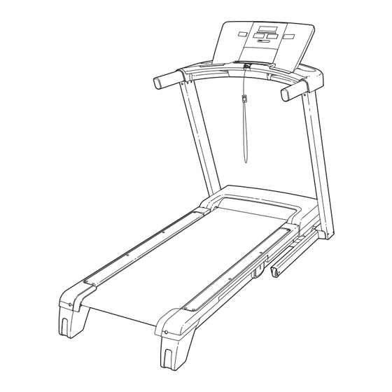
Model No. GGTL80608.0
Serial No.
Write the serial number in the space
above for reference.
Serial Number
Decal
QUESTIONS?
As a manufacturer, we are com-
mitted to providing complete cus-
tomer satisfaction. If you have
questions, or if parts are missing,
DO NOT CONTACT THE STORE;
please contact Customer Care.
IMPORTANT: You must note the
product model number and
serial number (see the drawing
above) before contacting us:
1-877-776-4777
CALL TOLL-FREE:
Mon.–Fri. 6 a.m.–6 p.m. MT
Sat. 8 a.m.–4 p.m. MT
ON THE WEB:
www.workoutwarehouse.com
CAUTION
Read all precautions and instruc-
tions in this manual before using
this equipment. Save this manual
for future reference.
With Universal Dock for iPod
USER'S MANUAL
®
Advertisement
Table of Contents

Subscribe to Our Youtube Channel
Related Manuals for Gold's Gym MAXX PERSONAL TRAINER 880


Summary of Contents for Gold's Gym MAXX PERSONAL TRAINER 880
- Page 1 With Universal Dock for iPod ® www.workoutwarehouse.com USER'S MANUAL Model No. GGTL80608.0 Serial No. Write the serial number in the space above for reference. Serial Number Decal QUESTIONS? As a manufacturer, we are com- mitted to providing complete cus- tomer satisfaction. If you have questions, or if parts are missing, DO NOT CONTACT THE STORE;...
-
Page 2: Table Of Contents
Apply the decal in the location shown. Note: The decals may not be shown at actual size. iPod is a trademark of Apple Computer, Inc., registered in the U.S. and other countries This product is manufactured and distributed under license from Gold's Gym Merchandising, Inc. -
Page 3: Important Precautions
IMPORTANT PRECAUTIONS WARNING: To reduce the risk of serious injury, read all important precautions and in- structions in this manual and all warnings on your treadmill before using your treadmill. ICON as- sumes no responsibility for personal injury or property damage sustained by or through the use of this product. - Page 4 20. Never leave the treadmill unattended while it 23. Never insert any object into any opening on is running. Always remove the key, unplug the treadmill. the power cord, and switch the reset/off cir- cuit breaker to the off position when the 24.
-
Page 5: Before You Begin
BEFORE YOU BEGIN Thank you for selecting the revolutionary GOLDʼS ing this manual, please see the front cover of this man- GYM MAXX™ PERSONAL TRAINER 880 treadmill ual. To help us assist you, note the product model with Universal Dock for iPod . -
Page 6: Assembly
ASSEMBLY To hire an authorized service technician to assemble the treadmill, call toll-free 1-800-445-2480. Assembly requires two persons. Set the treadmill in a cleared area and remove all packing materials. Do not dispose of the packing materials until assembly is completed. Note: The underside of the treadmill walking belt is coated with high-performance lubricant. - Page 7 1. Make sure that the power cord is unplugged. With the help of a second person, carefully tip the treadmill onto its left side. Partially fold the Frame (56) so that the treadmill is more stable; Hole do not fully fold the Frame yet. Remove and discard the two indicated bolts (A) and the shipping bracket (B).
- Page 8 4. Hold a Bolt Spacer (80) inside the lower end of the Right Upright (78). Insert a 3/8" x 4" Bolt (6) with a 3/8" Star Washer (9) into the Right Upright and the Bolt Spacer. Repeat this step with a second Bolt Spacer (80), 3/8" x 4" Bolt (6), and 3/8"...
- Page 9 7. Attach the Tray (90) to the handrail assembly with two #8 x 1/2" Screws (1). Have a second person hold the handrail assem- Handrail bly near the Right Upright (78) and the Left Assembly Upright (74). Connect the Upright Wire (38) to the console wire.
- Page 10 10. Insert the wires from the console assembly into the handrail assembly. Attach the console assembly to the handrail as- Console sembly with four 1/4" x 3/4" Bolts (5). Be careful Assembly not to pinch the wires. Handrail Assembly Wires 11.
- Page 11 If you purchase the optional chest pulse sensor (see page 22), follow the steps below to install the re- ceiver included with the chest pulse sensor. 1. Make sure that the power cord is unplugged. Remove the indicated #8 x 1/2" Screw (1) and the Access Door (87) from the Console Back Small (91).
-
Page 12: Operation And Adjustment
OPERATION AND ADJUSTMENT THE PRE-LUBRICATED WALKING BELT tric shock. This product is equipped with a cord having an equipment-grounding conductor and a grounding plug. Plug the power cord into a surge suppressor, Your treadmill features a walking belt coated with high- performance lubricant. - Page 13 CONSOLE DIAGRAM FEATURES OF THE CONSOLE step of your workout. One iFit card is included. Additional iFit cards are available separately. To purchase iFit cards at any time, call the tele- The treadmill console offers an impressive array of phone number on the front cover of this manual. features designed to make your workouts more effec- tive and enjoyable.
- Page 14 HOW TO TURN ON THE POWER HOW TO USE THE MANUAL MODE IMPORTANT: If the treadmill has been exposed to 1. Insert the key into the console. cold temperatures, allow it to warm to room tem- perature before turning on the power. If you do not See HOW TO TURN ON THE POWER at the left.
- Page 15 4. Change the incline of the treadmill as desired. The Fitness Age Calculator display— To change the incline of the treadmill, press the The Fitness Age Incline increase and decrease buttons or one of Calculator display is the numbered 1 Step Incline buttons. Each time used during the fitness you press one of the buttons, the incline will gradu- test and can show your...
- Page 16 6. Measure your heart rate if desired. one or two dashes will appear, and then your heart rate will be shown. For the most accurate heart rate reading, continue to hold the contacts for You can measure your heart rate using either the about 15 seconds.
- Page 17 HOW TO USE A PRESET WORKOUT The height of the flashing segment indicates the speed setting for the current segment. At the end of 1. Insert the key into the console. each segment, a series of tones will sound and the next segment of the profile will begin to flash.
- Page 18 HOW TO USE THE CUSTOM WORKOUT CENTER sents the current seg- Current Segment ment of the workout. The 1. Insert the key into the console. height of the flashing seg- ment indicates the speed See HOW TO TURN ON THE POWER on page setting for the current segment.
- Page 19 HOW TO USE THE FITNESS TEST WORKOUT Test button. Note: Pressing the Start Fitness Test button at this time will not start the fitness test The fitness test workout measures your approximate workout. fitness age. Your fitness age is the average age of someone at your fitness level.
- Page 20 HOW TO USE THE SOUND SYSTEM The workout is de- signed to last for nine minutes. When the This product has been designed specifically to work workout ends, the walk- with iPod and has been certified by the developer to ing belt will slow to a meet Apple performance standards.
- Page 21 HOW TO USE AN IFIT CARD cline setting are programmed for each segment. Note: The same speed setting and/or incline set- 1. Insert the key into the console. ting may be programmed for two or more consecu- tive segments. See HOW TO TURN ON THE POWER on page 3.
- Page 22 THE INFORMATION MODE THE OPTIONAL CHEST PULSE SENSOR The console features an information mode that keeps An optional chest pulse sensor offers hands-free oper- track of the total distance that the walking belt has ation as it tracks your heart rate during your workouts. To purchase the optional chest pulse sensor, call moved and the total number of hours that the treadmill the telephone number on the front cover of this...
-
Page 23: How To Fold And Move The Treadmill
HOW TO FOLD AND MOVE THE TREADMILL HOW TO FOLD THE TREADMILL FOR STORAGE Before folding the treadmill, adjust the incline to the lowest position. If you do not do this, you may damage the treadmill when you fold it. Remove the key and unplug the power cord. - Page 24 HOW TO LOWER THE TREADMILL FOR USE 1. Hold the upper end of the treadmill with your right hand. Pull the latch knob to the left and hold it. It may be neces- sary to push the frame forward as you pull the knob to the left.
-
Page 25: Troubleshooting
TROUBLESHOOTING Most treadmill problems can be solved by following the steps below. Find the symptom that applies, and follow the steps listed. If further assistance is needed, please see the front cover of this manual. PROBLEM: The power does not turn on SOLUTION: a. - Page 26 Remove the three #8 x 3/4" Screws (12) and care- fully pivot the Hood (61) off. Locate the Reed Switch (71) and the Magnet (50) on the left side of the Pulley (51). Turn the Pulley until the Magnet is aligned with the Reed Switch. Make sure that the gap between the Magnet and 1/8 in.
- Page 27 PROBLEM: The walking belt is off-center or slips when walked on SOLUTION: a. If the walking belt is off-center, first remove the key and UNPLUG THE POWER CORD. If the walking belt has shifted to the left, use the hex key to turn the left rear roller bolt clockwise 1/2 of a turn;...
-
Page 28: Exercise Guidelines
EXERCISE GUIDELINES WARNING: Burning Fat—To burn fat effectively, you must exer- cise at a low intensity level for a sustained period of Before beginning this time. During the first few minutes of exercise, your or any exercise program, consult your physi- body uses carbohydrate calories for energy. - Page 29 SUGGESTED STRETCHES The correct form for several basic stretches is shown at the right. Move slowly as you stretch—never bounce. 1. Toe Touch Stretch Stand with your knees bent slightly and slowly bend forward from your hips. Allow your back and shoulders to relax as you reach down toward your toes as far as possible.
-
Page 30: Part List
PART LIST—Model No. GGTL80608.0 R1108A To locate the parts listed below, see the EXPLODED DRAWING near the end of this manual. Key No. Qty. Description Key No. Qty. Description #8 x 1/2" Screw Front Roller/Pulley #8 x 1" Tek Screw 15 1/2"... - Page 31 Key No. Qty. Description Key No. Qty. Description Pulse Bar Ground Wire #8 Star Washer Latch Endcap #8 x 5/8" Screw iFit Card Kit 3/8" Jam Nut Lift Motor Spacer – 4" White Wire, M/F #8 x 2" Screw – Userʼs Manual Right Handrail Trim Note: Specifications are subject to change without notice.
-
Page 32: Exploded Drawing
EXPLODED DRAWING A—Model No. GGTL80608.0 R1108A... - Page 33 EXPLODED DRAWING B—Model No. GGTL80608.0 R1108A...
- Page 34 EXPLODED DRAWING C—Model No. GGTL80608.0 R1108A...
- Page 35 EXPLODED DRAWING D—Model No. GGTL80608.0 R1108A...
-
Page 36: Ordering Replacement Parts
ORDERING REPLACEMENT PARTS To order replacement parts, please see the front cover of this manual. To help us assist you, be prepared to pro- vide the following information when contacting us: • the model number and serial number of the product (see the front cover of this manual) •...
Need help?
Do you have a question about the MAXX PERSONAL TRAINER 880 and is the answer not in the manual?
Questions and answers