Table of Contents
Advertisement
Quick Links
Advertisement
Table of Contents

Subscribe to Our Youtube Channel
Related Manuals for Unimig RAZOR CUT 120


Summary of Contents for Unimig RAZOR CUT 120
- Page 1 RAZOR CUT 120 U14002K | Operating Manual...
-
Page 3: Table Of Contents
CONTENTS SAFETY TECHNICAL DATA MACHINE LAYOUT WHAT’S IN THE BOX GENERAL OPERATING TIPS DIGITAL SCREEN OPERATION CNC SETUP SETUP FOR INTERNAL AIR PLASMA CUTTING PLASMA CUTTING TECHNOLOGY PLASMA CUTTING TIPS & TECHNIQUES TORCH BREAKDOWN & SPARES MACHINE PARTS BREAKDOWN FAQ & TROUBLESHOOTING... -
Page 4: Safety
SAFETY Welding and cutting equipment can be dangerous to both the operator and people in or near the surrounding working area if the equipment is not correctly operated. Equipment must only be used under the strict and comprehensive observance of all relevant safety regulations. Read and understand this instruction manual carefully before the installation and operation of this equipment. - Page 5 SAFETY Fire hazard. Welding/cutting on closed containers, such as tanks, drums, or pipes, can cause them to explode. Flying sparks from the welding/cutting arc, hot workpiece, and hot equipment can cause fires and burns. Accidental contact of the electrode to metal objects can cause sparks, explosion, overheating, or fire. Check and be sure the area is safe before doing any welding/cutting.
- Page 6 SAFETY CAUTION 1. Working Environment. i. The environment in which this welding/cutting equipment is installed must be free of grinding dust, corrosive chemicals, flammable gas or materials etc., and at no more than a maximum of 80% humidity. ii. When using the machine outdoors, protect the machine from direct sunlight, rainwater and snow, etc.; the temperature of the working environment should be maintained within -10°C to +40°C.
-
Page 7: Technical Data
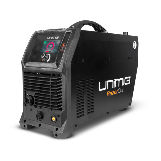
TECHNICAL DATA RAZOR™ CUT 120 Plasma Cutter Key Features: • CNC Connection • Pilot Arc Start • Digital Screen • 45mm Clean Cut • 60mm Severance • 2T/4T Torch Controls • Air Test TECHNICAL DATA PLASMA CUT SPECIFICATIONS SKU U14002K PLASMA CUT CURRENT RANGE 20-120A PRIMARY INPUT VOLTAGE 415V Three Phase 60% @ 120A... -
Page 8: Machine Layout
MACHINE LAYOUT Front Panel Layout 1. Selector Knob 2. Selector Button / Air Test Button 3. Digital Screen 4. Plasma Torch Connection 5. Earth Clamp Connection (10/25 Dinse) 6. CNC Connection Rear Panel Layout 7. Air Pressure Regulator Knob 8. Air Pressure Regulator Outlet Pressure Gauge 9. - Page 9 MACHINE LAYOUT Digital Screen Layout 12. Normal Cutting Mode 13. Current Display 14. Perforated Cutting Mode 15. Post-flow Display 16. Current Adjustment Selector 17. Post-flow Adjustment Selector 18. Bar Display...
-
Page 10: What's In The Box
• 1 x O ring • 1 x Cutting Tip • 1 x Retaining Cap • 1 x Stand Off Guide RAZOR CUT 120 Plasma Cutter 6m SC120 Plasma Torch 4m 300 AMP Earth Clamp Air Regulator RAZOR CUT 120... -
Page 11: General Operating Tips
GENERAL OPERATING TIPS Additional Machine Control Information Compressed Air Requirements A reliable and consistent supply of clean, dry compressed air is essential for proper operation. Although the machine contains its own internal air supply filtration system it is recommended the compressed air supply should have external filtration in the line feeding the machine, both a standard water trap (sintered bronze filter) and also a coalescing filter (for oil in the air). -
Page 12: Digital Screen Operation
DIGITAL SCREEN OPERATION Compressed Air Testing/Setting Hold the "Air Test" button for 2 seconds to enter the Air Test option, and the screen will display the above interface. As you continue to hold the "Air Test" button down, the air test will run. To end the air test, release the "Air Test"... - Page 13 DIGITAL SCREEN OPERATION Error Display 1. AIR Error Display The above interface is displayed when the machine has no gas input, or the air pressure is low. Correct air pressure is critical for plasma cutting. Incorrect air pressure will cause poor cut quality, a lack of cutting power, damage to the plasma torch and consumables and potentially damage to the power source.
- Page 14 DIGITAL SCREEN OPERATION System Setup Interface Hold the Selector Knob for 3 seconds to enter the settings interface. Press the Selector Button / Air Test Button to switch between the options (below) in the settings interface and set/adjust the parameters using the Selector Knob.
-
Page 15: Cnc Setup
CNC SETUP CNC Socket The RAZOR CUT 120 is equipped with an optional, factory-installed, four-position voltage divider that is designed to be safely connected without tools. The built-in voltage divider provides a scaled-down arc voltage of 20:1, 30:1, 40:1, and 50:1 (maximum output of 18V). An optional receptacle on the rear of the power supply provides access to the scaled-down arc voltage and signals for arc transfer and plasma start. -
Page 16: Setup For Internal Air Plasma Cutting
SETUP FOR INTERNAL AIR PLASMA CUTTING Connect the plasma torch to the plasma torch Connect the earth clamp to the positive (+) connection. Tighten the nut once connected to dinse connection, twist to lock in place ensure a secure connection. Connect the plug into power, then switch the Perform an Air Test by holding down the Air machine ON. - Page 17 SETUP FOR INTERNAL AIR PLASMA CUTTING Connect the earth clamp to the work piece. Select cutting mode by pressing the Selector Button until the desired cutting mode is highlighted. Set the current to turning the Selector Knob. Set the Post Flow (5-120s) by pushing the Selector Knob to cycle between Current and Post-Flow.
- Page 18 SETUP FOR INTERNAL AIR PLASMA CUTTING Place and hold the torch vertical at the edge of Pull the trigger to energise the arc. When the the plate. cutting arc has cut through the edge of the plate start moving evenly in the direction you wish to cut.
-
Page 19: Plasma Cutting Technology
PLASMA CUTTING TECHNOLOGY Plasma cutters work by passing an electric arc through a gas that is passing through a constricted opening. The electric arc elevates the temperature of the gas to the point that it enters a 4th state of matter. We all are familiar with the first three: i.e., Solid, liquid, and gas. -
Page 20: Plasma Cutting Tips & Techniques
PLASMA CUTTING TIPS & TECHNIQUES Amperage The standard rule of thumb is the thicker the material, the more amperage required. On thick material, set the machine to full output and vary your travel speed. On thinner material, you need to turn down the amperage and change to a lower-amperage tip to maintain a narrow kerf. - Page 21 The RAZOR CUT 120 air pressure must be adjusted and set to 0.5MPA (75psi) and requires a flow rate of 120 L/min. The volume capacity of your compressor is important. If you have a small compressor with precisely the same L/min rating as the plasma, then the compressor will run continuously when you are plasma cutting.
-
Page 22: Torch Breakdown & Spares
TORCH BREAKDOWN & SPARES SC120 Plasma Torch Gouging Contact Cutting Stand Off Cutting Part No. Length WG-SC120-60-CC1 TORCH SPARES TORCH SPARES SC1201 SC120 Torch Head Kit SC1232 Shield Cap Body SC8014 Plasma Handle Kit SC1251 Cutting Buggy SCSP1 Screw Pack SC1240 Stand-off Guide SC2516... -
Page 23: Machine Parts Breakdown
MACHINE PARTS BREAKDOWN MACHINE SPARES MACHINE SPARES 7.0510.0790 Right panel 3.0628.7006 Three-phase high frequency board 7.3010.0790 Machine cover 7.1230.038 cement resistor assembly sheet 7.2530.004 Handle 6.4450.001 cement resistor 7.0500.0790 Left panel 5.1850.0790 main transformer 7.1230.043 Gas valve assembly sheet 5.2710.0790 inductance 6.6240.103 T shape three way joint... -
Page 24: Faq & Troubleshooting
WARNING: There are extremely dangerous voltage and power levels present inside this unit. Do not attempt to diagnose or repair unit by removing external cover unless you are an authorised repair agent for UNIMIG. 1. Over Temp Error Display lamp on. - Page 25 NOTES...
- Page 26 NOTES...
- Page 27 NOTES...
- Page 28 PH: (02) 9780 4200 PH: (07) 3333 2855 PH: (03) 8682 9911 PH: (08) 6363 5111 FAX: (02) 9780 4210 FAX: (07) 3274 5829 FAX: (03) 9333 7867 FAX: (08) 9417 4781 EMAIL: sales@unimig.com.au EMAIL: qld@unimig.com.au EMAIL: vicsales@unimig.com.au EMAIL: wasales@unimig.com.au...
Need help?
Do you have a question about the RAZOR CUT 120 and is the answer not in the manual?
Questions and answers