
Related Manuals for Unimig KUPJR55


Summary of Contents for Unimig KUPJR55
- Page 1 OPERATING MANUAL KUPJR55 YEARS Warranty (Power Source) Please read and understand this instruction manual carefully before the installation and operation of this equipment. © Welding Guns Of Australia PTY LTD 2013...
-
Page 2: Warranty
UNIMIG welders and plasma cutters are manufactured to be compliant with - AS/NZ 60974-1, guaranteeing you electrical safety and performance. -
Page 3: Table Of Contents
Air Plasma Cutting Technology Technical Data, Product Information Machine Layout & Descriptions Set Up and Operating Procedure 10-12 Plasma Cutting Procedure & Techniques 13-15 T-100 & T-150 Plasma Torch Parts Breakdown 16-19 KUPJR55 Machine spare parts 20-21 Trouble Shooting Warranty terms 23-25... -
Page 4: Safety - Pre Cautions
SAFETY IMPORTANT: BEFORE INSTALLING, OPERATING OR CARRYING OUT MAINTENANCE ON THE PLASMA CUTTER, READ THE CONTENTS OF THIS MANUAL CAREFULLY, WHICH MUST BE STORED IN A PLACE FAMILIAR TO ALL USERS FOR THE ENTIRE OPERATIVE LIFE-SPAN OF THE MACHINE. PAY PARTICULAR ATTENTION TO THE SAFETY RULES. THIS EQUIPMENT MUST BE USED SOLELY FOR PLASMA CUTTING. - Page 5 Arc rays: harmful to people’s eyes and skin. Arc rays from the plasma cutting process produce intense visible and invisible ultraviolet and infrared rays that can burn eyes and skin. Protect your eyes with welding masks or goggles fitted with filtered lenses, and protect your body with appropriate safety garments.
-
Page 6: Working Environment
CAUTION 1. Working Environment. 1.1 The environment in which this Plasma Cutter equipment is installed must be free of grinding dust, corrosive chemicals, flammable gas or materials etc, and at no more than maximum of 80% humidity. 1.2 When using the machine outdoors protect the machine from direct sun light, rain water and snow etc; the temperature of working environment should be maintained within -10°C to +40°C. -
Page 7: Air Plasma Cutting Technology
AIR PLASMA CUTTING TECHNOLOGY Plasma cutters work by passing an electric arc through a gas that is passing through a constricted opening. The gas can be air, nitrogen, argon, oxygen. etc. The electric arc elevates the temperature of the gas to the point that it enters a 4th state of matter. -
Page 8: Technical Data, Product Information
The CUT55 is packaged with a tough T150 Plasma torch, earth lead and air regulator. The CUT55 gives you the power and performance to get the job done. Built to our specification and manufactured in compliance to AS/NZ60974-1 Product Code: KUPJR55 Standard option includes: CUT55 Machine, T150 Plasma Torch 6m, Earth Lead 25mm x 4m and Air Regulator. -
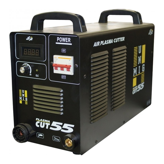
Page 9: Machine Layout & Descriptions
Front & Rear Panel Layout Front Panel Layout Rear Panel Layout (1) Digital Display (2) Over Current - Thermal Overload LED a. Abnormal or over current supply - LED ON b. Overheating of the machine - LED ON (3) Amperage Control Dial (4) Torch connection (DC-) (5) Output connector (DC+) connect to the work piece (6) Regulator bracket mounts... -
Page 10: Set Up And Operating Procedure
Set Up Procedure for PLASMA Cutting (1) Connect the T-150 Plasma Torch to the machine. Insert the torch connection into the torch connection receptacle at the front of the machine and screw up hand tight. Caution: Be careful not to bend the pins located inside the torch connector. (2) Connect the earth lead to the output terminal of the machine and tighten. - Page 11 PLASMA CENTRAL ADAPTOR Directions for use Attach the male connector (torch side) to the female one(machine side). Make sure that the positioning pin aligns (A) with the corresponding notch, and fasten the threaded ring (B). In order to fasten the ring (B), disengage the anti-rotation device by pressing it on proper hole (C) with the enclosed tool (D).
-
Page 12: Cut Quality
Operating Procedure for PLASMA Cutting Wear your safety gear. Generally you want Connect the Earth Clamp securely to Place and hold the torch vertical at the the same type of protective gear as when the work piece or the work bench. edge of the plate. -
Page 13: Plasma Cutting Procedure & Techniques
Operating Procedure & Techniques for PLASMA Cutting ● Amperage Standard rule of thumb is the thicker the material the more amperage required. On thick material, set the machine to full output and vary your travel speed. On thinner material, you need to turn down the amperage and change to a lower-amperage tip to maintain a narrow kerf. - Page 14 Operating Procedure & Techniques for PLASMA Cutting ● Air pressure and volume Air pressure, flow rate and air quality are critical to quality plasma cutting and consumable life span. The required air pressure and volume can vary from model to model and the manufacturer will provide the specs. The volume capacity of your compressor is important, if you have a small compressor with exactly the same l/min rating as the plasma, then the compressor will run continuously when you are plasma cutting, a compressor with a l/min rating slightly higher than the plasma would be more adequate.
- Page 15 Operating Procedure & Techniques for PLASMA Cutting ● Hand torch cutting technique When cutting make sure that sparks are If sparks are spraying up from the work Hold the torch vertical and watch the arc as exiting from the bottom of the work piece. piece, you are moving the torch too fast, or it cuts along the line.
-
Page 16: T-100 & T-150 Plasma Torch Parts Breakdown
PLASMA CUTTING TORCHES PLASMA CUTTING TORCHES PT25C T100 Plasma Torch & Spares Plasma Torch & Spares Air Cooled 25 Amp Air Cooled 100 Amp Technical Data Max Current: 150A Gas Pressure: 5.5 Bar Security System: Electrical Duty Cycle: Gas Flow: 220l/min Post Flow Time: 90 seconds... - Page 17 PLASMA CUTTING TORCHES PLASMA CUTTING TORCHES TD35 T100 Plasma Torch & Spares Plasma Torch & Spares Air Cooled 40 Amp Air Cooled 100 Amp Spare Parts Item WGA Part No. Description 01252 Hand torch complete with 6 mts cable (central connector) 01352 Hand torch complete with 12 mts cable (central connector) 01452...
- Page 18 PLASMA CUTTING TORCHES PLASMA CUTTING TORCHES PT25C T150 Plasma Torch & Spares Plasma Torch & Spares Air Cooled 25 Amp Air Cooled 150 Amp...
- Page 19 PLASMA CUTTING TORCHES PLASMA CUTTING TORCHES TD35 T150 Plasma Torch & Spares Plasma Torch & Spares Air Cooled 40 Amp Air Cooled 150 Amp Spare Parts Item WGA Part No. Description 04050/CS Hand torch complete with 6 mts cable (1/8” connection) 04051/CS Hand torch complete with 6 mts cable (central connector) 04151/CS...
-
Page 20: Kupjr55 Machine Spare Parts
Spare partS IdentIFIcatIon - KUpJr55 description part number TOP BOARD5 B01012 10000148 B01154 10000212 CENTER BOARD B02004 10000282 BOTTOM BOARD B03004 B03039 B03081 10000389 10000409 10000439 LOW VOLTAGE PCB B04010 10000510 HF PCB B06099 10 000 860 PTC PILOT ARC BOARD... - Page 21 Spare partS IdentIFIcatIon - KUpJr55...
-
Page 22: Trouble Shooting
TROUBLE SHOOTING - KUPJR55 WARNING There are extremely dangerous voltage and power levels present inside this unit. Do not attempt to diagnose or repair unit by removing external cover unless you are an authorised repair agent for UNIMIG. The cutting torch fails to ignite the arc, when torch trigger is pressed. -
Page 23: Warranty Terms
Fax: (02) 9780 4244 Welding Guns Of Australia Pty Ltd Email: sales@unimig.com.au / Web: www.unimig.com.au ABN: 14 001 804 422 Welding Guns Of Australia Pty Ltd (‘Us’, ‘We’) warrants that the following products under UNI-MIG, UNI-TIG, UNI-PLAS, UNI-FLAME, TECNA, T&R, HIT-8SS & ROTA, supplied by Us and purchased by you from an Authorised UNI-MIG, UNI-TIG, UNI-PLAS, UNI-FLAME, TECNA, T&R, HIT-8SS &... - Page 24 WARRANTY / RETURNS / EXCHANGES We understand that sometimes you may need to return a product you have purchased from Welding Guns Of Australia PTY LTD Authorised Dealer Network, to assist you, we have set out below the Welding Guns Of Australia PTY LTD Returns Policy that you should know.
- Page 25 WARRANTY EXCLUSIONS This Warranty covers Material and Faulty Workmanship defects only. This Warranty does not cover damage caused by: • Normal wear and tear due to usage • Misuse or abusive use of the UNI-MIG, UNI-TIG, UNI-PLAS, UNI-FLAME, TECNA, T&R, HIT-8SS & ROTA, instructions supplied with the product.
- Page 26 NOTES...
- Page 27 NOTES...
- Page 28 Welding Guns Of Australia PTY LTD 2013 Welding Guns Of Australia Pty Ltd ABN: 14 001 804 422 PO Box 3033, Lansvale NSW 2166, AUSTRALIA 112 Christina Rd, Villawood, NSW 2163 Phone: (02) 9780 4200 Fax: (02) 9780 4244 Email: sales@unimig.com.au / Web: www.unimig.com.au...
Need help?
Do you have a question about the KUPJR55 and is the answer not in the manual?
Questions and answers