
Related Manuals for Advanced Amplifiers AA-1M6G-30


Summary of Contents for Advanced Amplifiers AA-1M6G-30
- Page 1 Instruction Manual Including Quick Start Guide Advanced Amplifiers Solid State RF Amplifier System AA-1M6G-30 1 MHz - 6.0 GHz, 30 Watt, 45dB Min - Ver. 1.0 – 11-22 P a g e...
-
Page 2: Table Of Contents
Table of Contents SAFETY INSTRUCTIONS ................................3 SPECIFICATIONS ....................................4 ELECTRICAL SPECIFICATIONS: 50Ω, 25°C ........................4 ENVIRONMENTAL CHARACTERISTICS ........................... 4 MECHANICAL SPECIFICATIONS ............................4 OPERATING INSTRUCTIONS & GENERAL INFORMATION ................... 5 INTRODUCTION ..................................5 INCOMING INSPECTION ..............................5 RF & AC CABLE CONNECTION ............................5 RF TURN ON PROCEDURE .............................. -
Page 3: Safety Instructions
SAFETY INSTRUCTIONS BEFORE USING THIS EQUIPMENT Read this manual and become familiar with safety markings and instructions. Inspect unit for any sign of external damage. Do not use this equipment if there is physical damage or missing parts. Verify the input AC voltage to the main power supply. For a system with a digital controller option –... -
Page 4: Specifications
SPECIFICATIONS ELECTRICAL SPECIFICATIONS: 50Ω, 25°C Parameter Specification Notes Band Operating Frequency Band 1 - 1000 MHz 1 - 6 GHz Band switching @ 15 mS Max Power Output @ Psat 30 Watt Min / 50 Watt Typ CW or Pulse Power Gain 45 dB Min 0dBm or less for rated Pout... -
Page 5: Operating Instructions & General Information
EMI/EMC, communications, and various commercial and industry standards. With our in-house capabilities and fully equipped testing facilities, Advanced Amplifiers is committed to provide the best in RF products with industry leading quality and lead times. -
Page 6: Declaration Of Ce Conformity
Council Directive 2014/35/EC on Low Voltage Equipment Safety LIMITED WARRANTY Advanced Amplifiers warrants that goods delivered hereunder, at the time of delivery, will be free from defects in workmanship and material and will conform to the requirements of the purchase order. Seller’s liability hereunder shall be limited to the repair or replacement of defective goods F.O.B. -
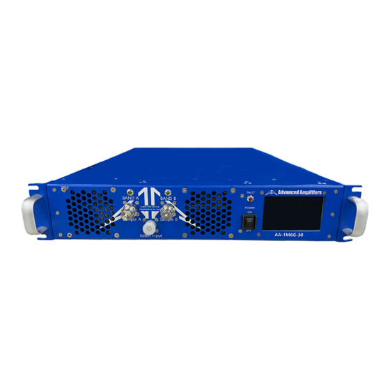
Page 7: Front & Rear Panel Descriptions
FRONT & REAR PANEL DESCRIPTIONS FRONT PANEL VIEW Title Function N Female, RF SAMPLE Connector. RF SAMPLE A SAMPLE PORT MUST BE TERMINATED AT ALL TIME N Female, RF SAMPLE Connector. RF SAMPLE B SAMPLE PORT MUST BE TERMINATED AT ALL TIME 0dBm INPUT N Female, 0dBm INPUT Connector. -
Page 8: Rear Panel View
REAR PANEL VIEW Title Function AC POWER CONNECTOR AC Power Input 100 ~ 240VAC, 47/63Hz, IEC60320-14 Connector. System RS-422 Communication / Gating Signal Female 9-Pin D-Sub Connector. P1 TX- P6 N/C P2 TX+ P7 N/C RS-422 P3 RX+ P8 N/C P4 RX- P9 N/C P5 GND (RS-422) -
Page 9: System Outline View
SYSTEM OUTLINE VIEW - Ver. 1.0 – 11-22 P a g e...
Need help?
Do you have a question about the AA-1M6G-30 and is the answer not in the manual?
Questions and answers