
Related Manuals for Advanced Amplifiers AMP2103P-LC


Summary of Contents for Advanced Amplifiers AMP2103P-LC
- Page 1 Instruction Manual Including Quick Start Guide Advanced Amplifiers Solid State RF Amplifier System AMP2103P-LC (AA-13G-500/1KWP) 0.8 – 3.2 GHz, 1000 Watt Pulse, 500W CW, 60 dB Min - Ver. 1.1 - 09-22 P a g e...
-
Page 2: Table Of Contents
Table of Contents SAFETY INSTRUCTIONS ............................... 3 SPECIFICATIONS ................................4 ELECTRICAL SPECIFICATIONS: 50Ω, 25°C ......................4 ENVIRONMENTAL CHARACTERISTICS ......................... 4 MECHANICAL SPECIFICATIONS ........................... 4 AVAILABLE SPECIAL OPTIONS ..........................4 OPERATING INSTRUCTIONS & GENERAL INFORMATION.................... 5 INTRODUCTION ..............................5 INCOMING INSPECTION ............................5 RF &... -
Page 3: Safety Instructions
SAFETY INSTRUCTIONS BEFORE USING THIS EQUIPMENT Read this manual and become familiar with safety markings and instructions. Inspect unit for any sign of external damage. Do not use this equipment if there is physical damage or missing parts. Verify the input AC voltage to the main power supply For a system with a digital controller option –... -
Page 4: Specifications
SPECIFICATIONS ELECTRICAL SPECIFICATIONS: 50Ω, 25°C Parameter Specification Notes Operating Frequency Range 0.8 - 3.2 GHz Power Output @ Pulse 1000 Watt Typ Peak Pulse Width Duty RF Rise/Fall Droop/O-shoot Pulse Characteristics up to 560µS up to 10% up to 10kHz 1 dB Typ 50nS Typ Power Output CW... -
Page 5: Operating Instructions & General Information
RF field for numerous applications including and not limited to, EMI/EMC, communications, and various commercial and industry standards. With our in-house capabilities and fully equipped testing facilities, Advanced Amplifiers is committed to provide the best in RF products with industry leading quality and lead times. -
Page 6: Declaration Of Ce Conformity
Council Directive 2014/35/EC on Low Voltage Equipment Safety LIMITED WARRANTY Advanced Amplifiers warrants those goods delivered hereunder, at the time of delivery, will be free from defects in workmanship and material and will conform to the requirements of the purchase order. Seller’s liability hereunder shall be limited to the repair or replacement of defective goods F.O.B. -
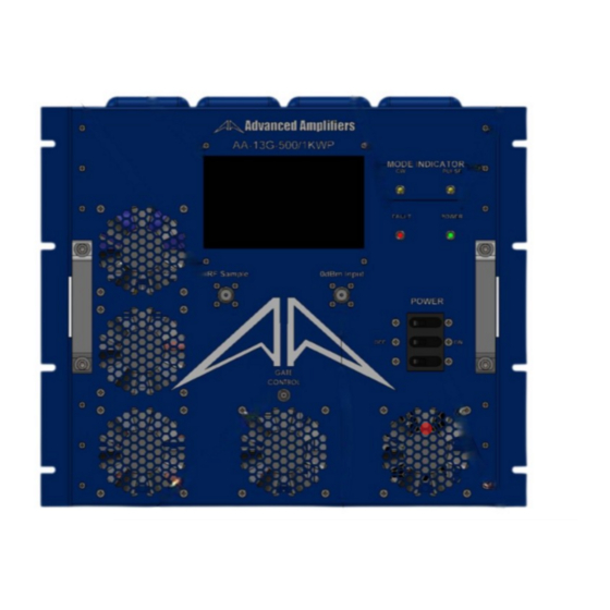
Page 7: Front & Rear Panel Descriptions
FRONT & REAR PANEL DESCRIPTIONS FRONT PANEL VIEW Title Function N Female, RF SAMPLE Connector. RF SAMPLE SAMPLE PORT MUST BE TERMINATED AT ALL TIME. LCD DISPLAY Touch screen LCD Display, System Control LCD Panel. FAULT LED System Fault LED: Turn ON an LED when Over-Temp, Ext. Shutdown. POWER LED Turn On a LED when Power Supply On. -
Page 8: Rear Panel View
REAR PANEL VIEW Title Function 50Ω OUTPUT N Female, 50Ω OUTPUT Connector. AC POWER AC Power Input 120 ~ 208VAC, 60Hz 3Phase, MS3102E MIL Connector. CONNECTOR GPIB IEEE-488 GPIB Interface Connector, Female. System RS-422 Communication / Gating Signal Female 9-Pin D-Sub Connector. -
Page 9: System Outline View
SYSTEM OUTLINE VIEW - Ver. 1.1 - 09-22 P a g e...
Need help?
Do you have a question about the AMP2103P-LC and is the answer not in the manual?
Questions and answers