
Related Manuals for Advanced Amplifiers AA-20M1G-50


Summary of Contents for Advanced Amplifiers AA-20M1G-50
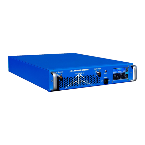
- Page 1 Instruction Manual and Quick Start Guide Exodus Advanced Communications Solid State RF Amplifier System AA-20M1G-50 20 - 1000 MHz, 50 Watt Min., 47 dB Min. P a g e - Ver. 1.0...
-
Page 2: Table Of Contents
Table of Contents SAFETY INSTRUCTIONS ............................3 SPECIFICATIONS ..............................4 ELECTRICAL SPECIFICATIONS..........................4 ENVIRONMENTAL CHARACTERISTICS ......................... 4 MECHANICAL SPECIFICATIONS..........................4 OPERATING INSTRUCTIONS & GENERAL INFORMATION ..................5 INTRODUCTION..............................5 INCOMING INSPECTION ............................5 RF & AC CABLE CONNECTION ..........................5 RF TURN ON PROCEDURE ........................... -
Page 3: Safety Instructions
OPTIONAL - IEEE-488 COMMAND LIST ......................... 26 ETHERNET INITIAL PARAMETER SETUP VIA USB CONNECTION ................27 MONITORING WINDOW ........................... 30 SAFETY INSTRUCTIONS BEFORE USING THIS EQUIPMENT Read this manual and become familiar with safety markings and instructions. Inspect unit for any sign of external damage. Do not use this equipment if there is physical damage or missing parts. -
Page 4: Specifications
SPECIFICATIONS ELECTRICAL SPECIFICATIONS: 50Ω, 25°C Parameter Specification Notes Operating Frequency Range 20 - 1000 MHz Power Output @ Psat 50 Watt Min Power Gain 47 dB Min Power Gain Flatness 3.0 dB p-p Max Input Return Loss -10 dB Max Relative to 50 Ohm 2-Tone Intermodulation (IMD) <-30 dBc Typ... -
Page 5: Operating Instructions & General Information
EMI/EMC and various commercial projects with all designing and manufacturing of our HPA, MPA, and LNA products in-house. Advanced Amplifiers received its ISO9001:2009 and ISO14001:2009 certification on January 2013 by ITQA which is an accredited member of JAS-ANZ. -
Page 6: Declaration Of Ce Conformity
Council Directive 2006/95/EC on Low Voltage Equipment Safety LIMITED WARRANTY Advanced Amplifiers warrants that goods delivered hereunder, at the time of delivery, will be free from defects in workmanship and material and will conform to the requirements of the purchase order. Seller’s liability hereunder shall be limited to the repair or replacement of defective goods F.O.B. -
Page 7: Front & Rear Panel Descriptions
FRONT & REAR PANEL DESCRIPTIONS FRONT PANEL VIEW RF Sample 0dBm Input AA-20M1G-50 FAULT POWER Title Function RF FOWARD System RF Forward Signal Sample Port, N type Female Connector. SAMPLE RF INPUT System RF Input Connector, N type Female Connector. -
Page 8: Rear Panel View
REAR PANEL VIEW 50Ω Output GPIB DEBUG AA-20M1G-50 RS-422 100 ~ 240 VAC 50/60Hz ETHERNET Title Function RF OUTPUT System RF Output Connector, N type Female Connector. USB Communication Connector, Type A Female. ETHERNET Ethernet Communication Female Connector, RJ-45. AC POWER AC Power Input 100 ~ 240 VAC, 50/60Hz, IEC60320-14 Connector. -
Page 9: System Outline View
SYSTEM OUTLINE VIEW RF Sample 0dBm Input AA-20M1G-50 FAULT POWER P a g e - Ver. 1.0... -
Page 10: System Block Diagram
SYSTEM BLOCK DIAGRAM TEMP SENSE FAN+ TEMP ALARM TEMP MONITOR CURR MONITOR INPUT DETECT 10 | P a g e - Ver. 1.0... -
Page 11: System View, Top Interior
SYSTEM VIEW, TOP INTERIOR 11 | P a g e - Ver. 1.0... -
Page 12: System View, Bottom
SYSTEM VIEW, BOTTOM INNER 12 | P a g e - Ver. 1.0... -
Page 13: System Parts List
SYSTEM PARTS LIST Part Number Qty. Description Input Module 40 x 28mm Cooling Fan Support 1 HPA Module Fan Controller Heat Sink RF Detect Module 1 Coupler Module 2 Support 2 Coupler Module 1 60 x 25mm Cooling Fan 60mm Cooling Fan Guard Temp Sensor RF Detect Module 2 Power Supply... -
Page 14: System Wiring Diagram
SYSTEM WIRING DIAGRAM 14 | P a g e - Ver. 1.0... -
Page 15: Local Controller Lcd Interface
APPENDIX 1 LOCAL CONTROLLER LCD INTERFACE SCREEN 1 (Illustrates unit in standby mode, showing table A parameters, fault indicator on, and output in Watt scale) ONLINE / STANDBY When the HPA system starts up, HPA goes into a standby mode. By pressing ONLINE button, unit goes into online (transmission) mode. -
Page 16: Screen 2
SCREEN 2 (Illustrates unit in standby mode, showing table B parameters, fault indicator on, and output in dBm scale) dBm / Watt This button enables FWD and RFL POWER readings to be in either WATT or dBm scale. TBL (B) (or Table (B)) Pending on system configurations, it will display some or all of below internal system parameters. -
Page 17: Screen 3
SCREEN 3 (Illustrates unit in standby mode, showing AGC setting under ALC menu, fault indicator on, and output in dBm scale) ATTEN GAIN CONTROL (or ATTENUATING GAIN CONTROL / AGC) This menu is active when ALC (Automatic Level Control) is OFF. This feature enables an operator to set the total gain of the system within 20 to 25dB range of maximum gain (If a total system gain is 50dB, maximum attenuation cannot exceed 50dB). -
Page 18: Screen 4
SCREEN 4: (Illustrates unit in standby mode, showing ALC setting under ALC menu, fault indicator on, and output in dBm scale) ALC CONTROL (or AUTOMATIC LEVEL CONTROL / ALC) This menu is active when ALC feature (Automatic Level Control) is ON. This feature enables an operator to set the total output of the system within 20 to 25dB range at a given output setting (If a total system output is 50dBm, maximum ALC level cannot be configured above 50dBm). -
Page 19: Screen 5
SCREEN 5: (Illustrates unit in standby mode, showing status windows under FAULT menu, fault indicator on, STAT shows CLEAR, FAULT, ALARM and output in dBm scale) FAULT Indications Pending on system configurations, FAULT section will display some or all of below monitoring parameters. OVER INPUT POWER Activates when input power to the system is greater than factory preset safe operating levels. -
Page 20: Remote Controller Interface Software
REMOTE CONTROLLER INTERFACE SOFTWARE PRIMARY (MAIN) WINDOW STANDY/ONLINE: Display system STANDY/ONLINE status. ONLINE/STANDY: System ONLINE/STANDY button. Watt/dBm: Watt/dBm conversion button. dBm/Watt: Display dBm/Watt status. TABLE/ALE/FAULT/COMM: Display menu status. TABLE: TABLE menu button. ALC: ALC menu button. FAULT: FAULT menu button. COMM: COMM menu button. -
Page 21: Alc On/Off Window
ALC ON/OFF Window ALC OFF Window ALC OFF: ALC OFF button. ALC ON: ALC ON button. SET ATTEN GAIN: Storing the attenuation value set to the system. Attenuation value setting window. Attenuation value setting button. READ CURR ATTEN GAIN: Import attenuation values stored in the system. ATTEN GAIN CONTROL: Display status when ALC OFF. -
Page 22: Alc On Window
ALC ON Window SET ALC: Storing the ALC value set to the system. ALC value setting window. ALC value setting button. READ CURR ALC: Import ALC values stored in the system. ALC CONTROL: Display status when ALC ON. ALC Off/ALC On: Display ALC operating status. 22 | P a g e - Ver. -
Page 23: Fault Window
FAULT Window Display status of the FAULT menu window. FAULT: Display menu status. 23 | P a g e - Ver. 1.0... -
Page 24: Comm Window
COMM Window BLUETOOTH: Select the BLUETOOTH communication selection button. ETHERNET: Select the ETHERNET communication selection button. IP CONFIG: IP, MAC address settings window button. SET PARA: The system default setting value button: Do not change setting! ERR LOG: System operation and FAULT message button. MONITORING: Data information window button at time the communication. -
Page 25: Ip Address Setup
IP ADDRESS SETUP Write to System: Save the IP or MAC address settings to the system. “1234”, written when saving password window (ⓔ). Read from System: Import IP or MAC address that is stored in the system. Write to File: Save the IP or MAC address settings to a text file. ETHERNET ENABLE / ETHERNET DISABLE: Enable or Disable ethernet. - Page 26 OPTIONAL - IEEE-488 COMMAND LIST Command Function Units Sets remote mode Sets local mode Select remote mode or local mode *IDN? Returns IEEE-488 Controller ID Returns the product model number SETID Sets the product model number Returns the product serial number SETSN Sets the product serial number DATE?
- Page 27 Command syntax example System over temperature setting: Set value 75℃ OVERT 0,75,C overt 0,75,C Overt 0,75,C OVERTEMperature 0,75,C overtemperature 0,75,C Overtemperature 0,75,C ETHERNET INITIAL PARAMETER SETUP VIA USB CONNECTION Note: All commands are not case sensitive. 1. Computer must have “Exodus CW System Monitor” program installed. This software comes with the manual package.
- Page 28 3. Click ‘COMM’ button. 4. Under communication menu, you will see a “USB” button (labeled ②) and a scroll down window for a communication port setting (labeled ③). Change the port number to the one that is assigned by your computer for this USB.
- Page 29 29 | P a g e - Ver. 1.0...
- Page 30 MONITORING WINDOW 7. Ethernet IP address setup - Click ‘COMMAND’ button (labeled ①) - In the command window (labeled ②), enter the IP address assigned to the system as shown in the example format below. > Ex) IP 220.89.108.100 (IP XXX.XX.XXX.XXX) - Click the ‘COM_SEND’...
- Page 31 - Click the ‘COM_SEND’ button (labeled ③). ▷ To confirm the entered TCP port. * Enter “TCP?” in the command window (labeled ②). * Click the ‘CMD_SEND’ button (labeled ③). * Check the ‘Receive’ window and it will show TCP? 1000 (TCP? XXXX). - In the command window (labeled ②), type “SYSTEMRESTART”...
- Page 32 32 | P a g e - Ver. 1.0...
- Page 33 Under the communication window, you will see a ‘TCP connected’ note (Labeled ②). System is now ready for remote monitoring and control. <IMPORTANT!> Time data window (labeled ③) should display current time when system is working properly. ML-AA-20M1G-50-032019 33 | P a g e...
Need help?
Do you have a question about the AA-20M1G-50 and is the answer not in the manual?
Questions and answers