Table of Contents
Advertisement
Available languages
Available languages
Quick Links
Advertisement
Chapters
Table of Contents
Troubleshooting

Related Manuals for Grozone Control TP24H


Summary of Contents for Grozone Control TP24H
- Page 1 USER GUIDE TP24H 24-Hour mer with High Temp Shut-Off www.grozonecontrol.com...
-
Page 2: Table Of Contents
TABLE OF CONTENTS SAFETY NOTICE PRODUCT DETAILS GENERAL DESCRIPTION 5-6-7 INSTALLATION & OPERATION SETTINGS 9-10-11 OPTIONAL SETTINGS 12-13 QUICK TROUBLESHOOTING GUIDE 14-15 COMPLETE TROUBLESHOOTING GUIDE 16-17 WARRANTY & CUSTOMER SERVICE 18-19... -
Page 3: Safety Notice
SAFETY NOTICE IMPORTANT SAFETY INSTRUCTIONS SAVE THESE INSTRUCTIONS DANGER TO REDUCE THE RISK OF FIRE OR ELECTRIC SHOCK, CAREFULLY FOLLOW THESE INSTRUCTIONS. To reduce the risk of electric shock, disconnect power to the 120V electrical outlet before installing or removing the unit. When removing the electrical wall plate, it may fall across plug pins or become displaced. -
Page 4: Product Details
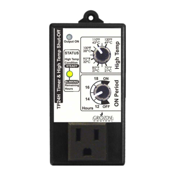
PRODUCT DETAILS Opera on and Specifica ons Temperature setpoint between 70°F and 120°F (21°C to 49°C). 6- temperature probe works from +32°F to +212°F (0°C to 100°C). On mes range from 12, 14, 16 and 18 hours. On/Off Status at power up is adjustable. Internal 24-hour Clock precision : Less than 30 minutes per year. -
Page 5: General Description
ON cycles from 12 to 18 hours. Delay A 20-minute Output ON delay is ac ve when: 120V power is applied to the TP24H OR when power returns a er a pow- · er outage. See "Note 1" A high temperature condi on is met. If the room cools down in less than ·... - Page 6 GENERAL DESCRIPTION Status LED ON: The Status Led turns on when a High Temperature condi on is met. OFF: The Status Led turns off when the lower knob is in ON or OFF posi- BLINKING: The Status Led is blinking to indicate the remaining me (number of hours le in the current cycle).
- Page 7 GENERAL DESCRIPTION Output ON LED ON: The Output ON Led is ON when there is power applied to the 120V front panel output. OFF: The Output ON Led is OFF when there is no power applied to the 120V front panel output (during OFF cycles or when a high temperature condi on is present).
-
Page 8: Installation & Operation
INSTALLATION & OPERATION Values Se ng Output On High Temp ON Period Plug into 120 VAC outlet (see security no ce on page 1). Place the sensor at desired loca on. Connect your equipment in the front panel outlet (MAX 15A). Installa on is now complete... -
Page 9: Settings
SETTINGS Cycles Se ng To start a new ON cycle A. Unplug unit. B. Set lower knob to ON. C. Plug in the unit and wait 2 seconds. D. Set lower knob from 18 to 12 hours. - Page 10 SETTINGS Cycles Se ng To start a new OFF cycle A. Unplug unit. B. Set lower knob to OFF. C. Plug in the unit and wait 2 seconds. D. Set lower knob from 12 to 18 hours.
- Page 11 SETTINGS High Temperature Se ngs The output will turn OFF as soon as the ambient temperature reaches this se ng. The output will turn back ON when the ambient tempera- ture has cooled down by 5°F (or 10°F, see "Op onal Se ng") or when the output remained OFF for a minimum of 20 minutes.
-
Page 12: Optional Settings
OPTIONAL SETTINGS/5°F COOL DOWN The TP24H has been set to perform in 5°F Setback (cool down). Change to 5°F cool down A. Unplug the unit. Set both knobs fully clockwise. B. Within 5 seconds, plug in the unit then set both knobs fully counter clockwise. - Page 13 Change to 10°F cool down A. Unplug the unit. Set both knobs fully counter clockwise. B. Within 5 seconds, plug in the unit then set both knobs fully clockwise. C. "Output ON" light indicator turns OFF. TP24H is now in 10°F cool down...
-
Page 14: Quick Troubleshooting Guide
QUICK TROUBLESHOOTING GUIDE... - Page 15 QUICK TROUBLESHOOTING GUIDE...
-
Page 16: Complete Troubleshooting Guide
COMPLETE TROUBLESHOOTING GUIDE 24-Hour Timer with High Temp Shut-off TP24H 1 – Before you start ***IMPORTANT: READ AND FOLLOW THESE INSTRUCTIONS BEFORE STARTING THE TEST. DO NOT CONNECT UNIT BEFORE STEP 1 OF THE TEST. · CONNECT A LOAD INTO THE UNIT. - Page 17 COMPLETE TROUBLESHOOTING GUIDE STEPS HANDLING AND TEST DESCRIPTIONS EXPECTED RESULTS Lower knob check Turn lower knob fully counter The Output ON light · clockwise (OFF). indicator and the Status light indicator will turn OFF. Turn lower knob to 12H. The Output ON light ·...
-
Page 18: Warranty & Customer Service
WARRANTY & CUSTOMER SERVICE DO YOU HAVE A PROBLEM WITH YOUR CONTROLLER ? PLEASE READ THESE INSTRUCTIONS CAREFULLY AND SAVE THEM FOR FUTURE REFERENCE. 1. I think my controller is damaged, or it simply does not work as indicated in the user guide, what should I do? Please refer to the troubleshoo ng steps. - Page 19 To avoid being charged for the accessories, be sure to include all pieces. Thanks for your coopera on. Any Grozone Control product that is returned with obvious signs of user · neglect will not be covered by the warranty. Grozone Control exercises the right to make final decisions in these ma ers.
- Page 21 Guide de l’usager TP24H Minuterie 24 heures avec coupe-circuit en haute température www.grozonecontrol.com...
- Page 22 TABLE DES MATIÈRES NOTICE DE SÉCURITÉ FICHE DE PRODUIT DESCRIPTION GÉNÉRALE 5-6-7 INSTALLATION & OPÉRATION RÉGLAGES 9-10-11 RÉGLAGES OPTIONNELS 12-13 GUIDE DE DÉPANNAGE RAPIDE 14-15 GUIDE DE DÉPANNAGE COMPLET 16-17 SERVICE À LA CLIENTÈLE ET GARANTIE 18-19...
-
Page 23: Notice De Sécurité
NOTICE DE SÉCURITÉ INSTRUCTIONS DE SÉCURITÉ IMPORTANTES CONSERVEZ CES INSTRUCTIONS DANGER POUR RÉDUIRE LES RISQUES D'INCENDIE OU DE CHOCS ÉLECTRIQUES, SUIVRE ATTENTIVEMENT CES INSTRUCTIONS. Pour réduire le risque de chocs électriques, coupez le courant de la prise de courant avant d'installer ou d'enlever l'unité. En enlevant la vis retenant le couvercle de la prise 120V, celui-ci peut tomber sur les fiches et les court-circuiter, ou encore la prise pourrait se déplacer. -
Page 24: Fiche De Produit
FICHE DE PRODUIT Fonc onnement et caractéris ques Consigne de Température entre 70°F et 120°F (21°C à 49°C). Sonde de 6 pieds pouvant travailler de 0°C à 100°C (32°F à 212°F). Cycle ON de 12, 14, 16 et 18 heures. Le statut ON/OFF au démarrage est ajustable. -
Page 25: Description Générale
DESCRIPTION GÉNÉRALE Le TP24H est une minuterie 24 heures avec coupe circuit en haute tem- pérature servant à contrôler un système d’éclairage, 2 ballasts de 600 Wa s ou un ballast de 1000 Wa s à 120V et perme ant des cycles ON de 12 à... - Page 26 DESCRIPTION GÉNÉRALE Indicateur lumineux: Status ON: L’indicateur lumineux Status s’allume quand une condi on de haute température survient. OFF: L’indicateur lumineux Status s’éteint quand le bouton du bas est posi onné à ON ou à OFF. CLIGNOTEMENT: L’indicateur lumineux Status clignote pour indiquer le décompte du cycle en cours.
- Page 27 TP24H. OFF: L’indicateur lumineux Output ON s’éteint quand il n’y a pas de cou- rant sur la sor e du TP24H (pendant les cycles OFF où en condi on de haute température). CLIGNOTEMENT: L’indicateur lumineux Output ON clignotera quand la sor e devrait être ac ve mais ne l’est pas à...
-
Page 28: Installation & Opération
ON Period Branchez dans une prise 120 VAC (voir la no ce de sécurité à la page 1). Placez le capteur de température à l’endroit désiré. Branchez votre équipement dans la prise du TP24H (MAX 15A). L’installa on est complétée... -
Page 29: Réglages
RÉGLAGES Ajustement des cycles Pour réini aliser en cycle ON A. Débranchez le module. B. Ajustez le bouton du bas à ON. C. Branchez le module et a endez 2 secondes. D. Ajustez le bouton du bas de 12 à 18 heures. - Page 30 RÉGLAGES Ajustement des cycles Pour réini aliser en cycle Off A. Débranchez le module. B. Ajustez le bouton du bas à OFF. C. Branchez le module et a endez 2 secondes. D. Ajustez le bouton du bas de 12 à 18 heures.
- Page 31 RÉGLAGES Ajustement de la limite de haute température Le module désac vera la sor e aussitôt que la température ambiante a eindra la limite de haute température définie par l’usager. Le module réac vera la sor e seulement quand la température ambiante aura descendu de 5°F (ou 10°F, voir sec on "Réglages Op onnels") ou aura a eint la fin du délai de 20 minutes.
-
Page 32: Réglages Optionnels
A. Débranchez l’unité. Tournez les boutons complètement dans le sens horaire. B. En moins de 5 secondes, branchez l’unité et tournez les boutons complètement dans le sens an horaire. C. Le témoin "Output ON" s’allume. Votre TP24H est maintenant en mode refroidissement 5°F... - Page 33 A. Déranchez l’unité. Tournez les boutons complètement dans le sens an horaire. B. En moins de 5 secondes, branchez l’unité et tournez les boutons complètement dans le sens horaire. C. Le témoin "Output ON" s’éteint. Votre TP24H est maintenant en mode refroidissement 10°F...
-
Page 34: Guide De Dépannage Rapide
GUIDE DE DÉPANNAGE RAPIDE... - Page 35 GUIDE DE DÉPANNAGE RAPIDE...
-
Page 36: Guide De Dépannage Complet
GUIDE DE DÉPANNAGE COMPLET Minuterie 24 heures avec coupe-circuit en haute température TP24H 1 – La prépara on avant test ***IMPORTANT : LIRE ET APPLIQUER LES ÉTAPES DE PRÉPARATION SUIVANTES AVANT DE COMMENCER LE TEST. NE PAS BRANCHEZ L’UNITÉ AVANT L’ÉTAPE 1 DU TEST. - Page 37 GUIDE DE DÉPANNAGE COMPLET ÉTAPE MANIPULATION ET TEST À EFFECTUER RÉSULTAT ATTENDU Bouton inférieur Tournez le bouton inférieur L’indica f lumineux · complètement dans le S.A.M. (OFF). Output ON et l’indicateur lumineux Status s’éteindront. Tournez le bouton inférieur à 12H. L’indicateur lumineux ·...
-
Page 38: Service À La Clientèle Et Garantie
SERVICE À LA CLIENTÈLE ET GARANTIE AVEZ-VOUS RENCONTRÉ UN PROBLÈME AVEC VOTRE CONTRÔLEUR ? SVP LIRE CES INSTRUCTIONS AVEC ATTENTION ET CONSERVEZ-LES POUR Y RÉFÉRER ULTÉRIEUREMENT 1. Je pense que mon contrôleur est endommagé ou encore il ne fonc onne simplement pas comme décrit dans le manuel, que dois-je faire ? Référez-vous aux étapes de dépannage. - Page 39 2. J’ai suivi les étapes de dépannage, que dois-je faire si je rencontre un problème à l’une ou l’autre des étapes ? Mon produit est-il couvert par la garan e ? Les contrôleurs Grozone Control sont couverts par une garan e de 3 · ans(*). NOUS REMPLAÇONS TOUT PRODUIT ENDOMMAGÉ PAR UN PRODUIT NEUF.
- Page 40 Rev. 4.0 www.grozonecontrol.com...
Need help?
Do you have a question about the TP24H and is the answer not in the manual?
Questions and answers