Advertisement
Quick Links
Converter with Power System Management
DESCRIPTION
Demonstration circuit 2652A-B is an 8-phase dual-output,
high efficiency, high density, synchronous buck converter
with 7V to 14V input range. Each output can supply up to
120A maximum load current with 1V output. The demo
board showcases the
LTC
compliant dual loop 8-phase step-down DC/DC controller
with digital power system management. The LTC3888-1
is designed to work with DrMOS devices that provide an
output current sense and temperature monitor. Please
see LTC3888-1's datasheet for more detailed information.
DC2652A-B powers up to default settings and produces
power based on configuration resistors (or with the set-
ting in its non-volatile memory) without the need for any
serial bus communication. This allows easy evaluation of
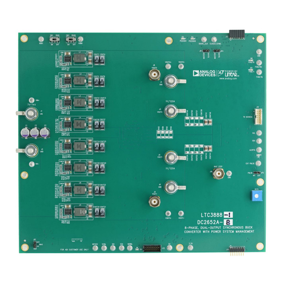
BOARD PHOTO
8-Phase, Dual-Output Synchronous Buck
3888-1, which is a PMBus-
®
Figure 1. Dual-Output LTC3888-1/DC2652A-B Demo Circuit
DEMO MANUAL DC2652A-B
the DC/DC converter. To fully explore the extensive power
system management features of the part, download the
GUI software LTpowerPlay™ onto your PC and use ADI's
2
I
C/SMBus/PMBus dongle DC1613A to connect to the
board. LTpowerPlay allows the user to reconfigure the part
on the fly and store the configuration in EEPROM, view
telemetry of voltage, current, temperature and fault status.
GUI Download
The software can be downloaded from:
For more details and instructions of LTpowerPlay, please
refer to "LTpowerPlay Quick Start Procedure".
Design files for this circuit board are
All registered trademarks and trademarks are the property of their respective owners.
LTC3888-1
LTpowerPlay
available.
Rev. 0
1
Advertisement

Related Manuals for Linear ANALOG DEVICES LTC3888-1


Summary of Contents for Linear ANALOG DEVICES LTC3888-1
- Page 1 DEMO MANUAL DC2652A-B LTC3888-1 8-Phase, Dual-Output Synchronous Buck Converter with Power System Management DESCRIPTION Demonstration circuit 2652A-B is an 8-phase dual-output, the DC/DC converter. To fully explore the extensive power high efficiency, high density, synchronous buck converter system management features of the part, download the with 7V to 14V input range.
-
Page 2: Quick Start Procedure
DEMO MANUAL DC2652A-B PERFORMANCE SUMMARY Specifications are at T = 25°C PARAMETER CONDITIONS UNITS Input Voltage Range 7V to 14V Output Voltage, V = 7 to 14V, I = 0A to 120A 0.3 to 1.8V, Default: 1.0V OUT0 OUT0 Maximum Output Current, I = 7 to 14V, V = 0.3V to 1.8V 120A... - Page 3 DEMO MANUAL DC2652A-B QUICK START PROCEDURE Figure 2. Proper Measurement Equipment Setup Figure 3. Measuring Output Voltage Ripple Rev. 0...
- Page 4 DEMO MANUAL DC2652A-B QUICK START PROCEDURE Connecting a PC to DC2652A-B margin set points, OV/UV limits, temperature fault limits, sequencing parameters, the fault log, fault responses, You can use a PC to reconfigure the power management GPIOs and other functionalities. The DC1613A dongle features of the LTC3888-1 such as: nominal VOUT, may be plugged when VIN is present.
- Page 5 DEMO MANUAL DC2652A-B QUICK START PROCEDURE OUT0 OUT1 (20MHz BW) (20MHz BW) 50mV/DIV 50mV/DIV OUT0 OUT1 0A-30A LOAD STEP 0A-30A LOAD STEP 20A/DIV 20A/DIV 100 s/DIV 100 s/DIV Figure 7. V Load Transient Response at V = 12V, Figure 8. V Load Transient Response at V = 12V, OUT0 OUT1...
- Page 6 DEMO MANUAL DC2652A-B LTPOWERPLAY SOFTWARE GUI LTpowerPlay is a powerful Windows based development a system, or to diagnose power issues when bringing environment that supports Analog Devices power system up rails. LTpowerPlay utilizes the DC1613A USB-to-I management ICs and μModules, including LTM4675, SMBus/PMBus controller to communicate with one of LTM4676, LTM4677, LTM4678, LTM4680, LTM4700, many potential targets, including LTM4675, LTM4676,...
- Page 7 DEMO MANUAL DC2652A-B LTPOWERPLAY QUICK START PROCEDURE The following procedure describes how to use LTpower- Play to monitor and change the settings of LTC3888-1. 1.Download and install the LTpowerPlay GUI: 2. Launch the LTpowerPlay GUI. a. The GUI should automatically identify the DC2652A-B. The system tree on the left hand side should look like this: Then, click the W (PC to RAM) icon to write these register values to the LTC3888-1.
- Page 8 DEMO MANUAL DC2652A-B PARTS LIST ITEM REFERENCE PART DESCRIPTION MANUFACTURER/PART NUMBER Required Circuit Components C1, C2, C3, C4, C5, C6 CAP ., 270uF , ALUM, 16V, 20%, SMD 8x11.9mm, E12 PANASONIC/16SVPC270M COUT1, COUT2, COUT6, CAP ., 100uF , X5R, 6.3V, 20%, 1210 AVX/12106D107MAT2A COUT7, COUT10, COUT11, COUT14,...
- Page 9 DEMO MANUAL DC2652A-B PARTS LIST ITEM REFERENCE PART DESCRIPTION MANUFACTURER/PART NUMBER C114 CAP ., 5.6pF, C0G/NP0, 50V, +/-0.25pF, 0603 AVX/06035A5R6CAT2A C116 CAP ., 100pF, C0G/NP0, 25V, 5%, 0603 AVX/06033A101JAT2A DIODE, SCHOTTKY, 200V, 1A, PowerDI-123, DIODES INC./DFLS1200-7 AEC-Q101 L1, L2, L3, L4, L5, L6, IND., 215nH, PWR, FERRITE, 10%, 61A, 0.29mOHM, EATON/FP1007R3-R22-R L7, L8...
- Page 10 DEMO MANUAL DC2652A-B PARTS LIST ITEM REFERENCE PART DESCRIPTION MANUFACTURER/PART NUMBER COUT39, COUT60, CAP ., 470uF , TANT, POSCAP , 2.5V, 20%, 7343, TPF PANASONIC/ETPF470M5H COUT61, COUT63 Series COUT40, COUT41, CAP ., 100uF , X5R, 6.3V, 20%, 1210 AVX/12106D107MAT2A COUT42, COUT44, COUT47, COUT48, COUT55, COUT56, C84, COUT43, COUT49...
- Page 11 DEMO MANUAL DC2652A-B PARTS LIST ITEM REFERENCE PART DESCRIPTION MANUFACTURER/PART NUMBER R4, R7, R11, R26, R33, RES., OPTION, 0402 R35, R56, R60, R62, R70, R73, R77, R84, R87, R92, R100, R103, R106, R114, R118, R120, R128, R132, R134 R28, R30, R166, R198, RES., 0 OHM, 1/10W, 0603, AEC-Q200 NIC/NRC06ZOTRF R200, R202, R203, R257,...
- Page 12 DEMO MANUAL DC2652A-B PARTS LIST ITEM REFERENCE PART DESCRIPTION MANUFACTURER/PART NUMBER R209 RES., OPTION, 1206 R214, R215, R216, RES., 2k OHMS, 1%, 1/10W, 0603, AEC-Q200 KOA SPEER/RK73H1JTTD2001F R217, R219 R220 RES., 15.8k OHMS, 1%, 1/10W, 0603, AEC-Q200 NIC/NRC06F1582TRF R233 RES., 2k OHMS, 1%, 1/10W, 0603, AEC-Q200 KOA SPEER/RK73H1JTTD2001F R258 RES., 0 OHM, 1/8W, 0805...
- Page 13 DEMO MANUAL DC2652A-B PARTS LIST ITEM REFERENCE PART DESCRIPTION MANUFACTURER/PART NUMBER Hardware: For Demo Board Only XJP1, XJP2, XJP3, XJP4 CONN., SHUNT, FEMALE, 2 POS, 2mm WURTH/60800213421 MP1, MP2, MP3, MP4, STANDOFF , NYLON, SNAP-ON, 0.50 WURTH/702935000 MP5, MP6, MP7, MP8 E1, E2, E3, E4, E5, E6, TEST POINT, TURRET, 0.094 MTG.
- Page 14 DEMO MANUAL DC2652A-B SCHEMATIC DIAGRAM Rev. 0...
- Page 15 DEMO MANUAL DC2652A-B SCHEMATIC DIAGRAM Rev. 0...
- Page 16 DEMO MANUAL DC2652A-B SCHEMATIC DIAGRAM Rev. 0...
-
Page 17: Schematic Diagram
DEMO MANUAL DC2652A-B SCHEMATIC DIAGRAM Rev. 0... - Page 18 DEMO MANUAL DC2652A-B SCHEMATIC DIAGRAM Rev. 0...
- Page 19 DEMO MANUAL DC2652A-B SCHEMATIC DIAGRAM Rev. 0...
- Page 20 DEMO MANUAL DC2652A-B SCHEMATIC DIAGRAM Rev. 0...
- Page 21 DEMO MANUAL DC2652A-B SCHEMATIC DIAGRAM Rev. 0 Information furnished by Analog Devices is believed to be accurate and reliable. However, no responsibility is assumed by Analog Devices for its use, nor for any infringements of patents or other rights of third parties that may result from its use. Specifications subject to change without notice.
- Page 22 DEMO MANUAL DC2652A-B ESD Caution ESD (electrostatic discharge) sensitive device. Charged devices and circuit boards can discharge without detection. Although this product features patented or proprietary protection circuitry, damage may occur on devices subjected to high energy ESD. Therefore, proper ESD precautions should be taken to avoid performance degradation or loss of functionality. Legal Terms and Conditions By using the evaluation board discussed herein (together with any tools, components documentation or support materials, the Evaluation Board), you are agreeing to be bound by the terms and conditions set forth below (Agreement) unless you have purchased the Evaluation Board, in which case the Analog Devices Standard Terms and Conditions of Sale shall govern.
Need help?
Do you have a question about the ANALOG DEVICES LTC3888-1 and is the answer not in the manual?
Questions and answers