Advertisement
Quick Links
Description
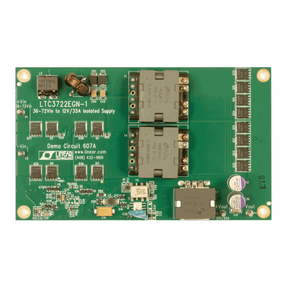
Demonstration circuit 607A is an isolated full bridge
converter featuring the LTC3722, LTC4440, LTC3901,
and LT1431. This circuit was designed to demonstrate the
phase-shifted full bridge power supply to generate 12V
at 35A from a typical telecom input voltage range of 36V
to 72V. Isolation voltage is 1500VDC. Fixed zero-voltage
transition timing was chosen because of the relatively fast
performance summary
SYMBOL
PARAMETER
V
Input Supply Range
IN
V
Output Voltage
OUT
I
Output Current Range
OUT
f
Switching (Clock) Frequency
SW
V
Output Ripple
OUT(P-P)
I
Output Regulation
REG
P
/P
Efficiency
OUT
IN
P
/P
Efficiency
OUT
IN
Isolation
Approximate Size
operating principles
The LTC3722 synchronous dual mode phase modulated
full bridge controller is used on the primary and works
together with the LTC3901 secondary side synchronous
driver to provide a synchronous rectified output. When an
input voltage is applied, the LTC3722 begins a controlled
soft-start of the output voltage. As this voltage begins
to rise, the LT1431 programmable reference is quickly
powered up via the output voltage. The LT1431 provides
feedback via opto-coupler ISO1 to set the output voltage
at 12V. The LTC4440 high voltage gate driver is used to
level shift the high side primary MOSFETs gate signals.
DEMO MANUAL DC607A
LTC3722, LTC4440, LTC3901,
Isolated Full Bridge Converter
bridge leg transition times with a 48V input. The DC607A
PCB layout includes options to implement adaptive timing.
Design files for this circuit board are available at
http://www.linear.com/demo/DC607A
L, LT, LTC, LTM, Linear Technology and the Linear logo are registered trademarks of Analog
Devices, Inc. All other trademarks are the property of their respective owners.
Specifications are at T
A
CONDITIONS
V
= 48V, 200LFM
IN
V
= 48V, I
= 35A (20MHz BW)
IN
OUT
Line and Load (36V to 72V, 0A to 35A)
V
= 48V, I
= 35A
IN
OUT
V
= 48V, I
= 25A
IN
OUT
Basic
Component Area × Top Component Height
The LTC3722 provides precise control of gate signals to
primary MOSFETs and secondary MOSFETs via T3 and
U1 (LTC3901). The LTC3901 includes a timer and current
sense to limit reverse inductor current.
For large values of input inductance, a 100V, 47µF electro-
lytic capacitor can be added across the input terminals to
damp the input filter and provide adequate stability. See
Linear Technology Application Note 19 for a discussion
on input filter stability analysis. A recommended part is
the SUNCON 100ME47AX.
= 25°C
MIN
36
0
4.3 × 2.9 × 0.4
and LT1431
TYP
MAX
UNITS
72
V
12.0
V
35
A
200
kHz
140
mV
P-P
±0.08
%
>93.9
%
>94.6
%
1500
VDC
Inches
dc607afa
1
Advertisement

Related Manuals for Linear LTC4440


Summary of Contents for Linear LTC4440
- Page 1 35A from a typical telecom input voltage range of 36V L, LT, LTC, LTM, Linear Technology and the Linear logo are registered trademarks of Analog to 72V. Isolation voltage is 1500VDC. Fixed zero-voltage Devices, Inc. All other trademarks are the property of their respective owners.
-
Page 2: Quick Start Procedure
Demonstration circuit 607A is easy to set up to evaluate 3. Turn on the power at the input. the performance of the LTC3722, LTC4440, LTC3901, NOTE. Make sure that the input voltage never exceeds and LT1431. Refer to Figure 1 for proper measurement 72V. - Page 3 DEMO MANUAL DC607A Quick start proceDure Figure 1. Proper Measurement Equipment Setup Figure 2. Measuring Input or Output Ripple dc607afa...
- Page 4 DEMO MANUAL DC607A Quick start proceDure Figure 3. Transient Response, 0A to 35A, 48V (200mV and 0.5ms/Div) dc607afa...
- Page 5 DEMO MANUAL DC607A Quick start proceDure Figure 4. Thermal Map, 48V , 12V at 35A , 200LFM, Frontside Figure 5. Thermal Map, 48V , 12V at 35A , 200LFM, Backside dc607afa...
- Page 6 DEMO MANUAL DC607A Quick start proceDure Figure 6. Thermal Map, 48V , 12V at 35A , 400LFM, Frontside Figure 7. Thermal Map, 48V , 12V at 35A , 400LFM, Backside dc607afa...
-
Page 7: Parts List
DEMO MANUAL DC607A parts list ITEM REFERENCE PART DESCRIPTION MANUFACTURER/PART NUMBER Required Circuit Components C1, C2, C3, C4, C5, C46 CAP, X7R, 0.82µF, 100V, 10%, 1812 VISHAY, VJ1812Y824KXBAT C24, C31 CAP, X7R, 1µF, 25V, 10%, 1206 AVX, 12063C105KAT2A CAP, NPO, 470pF, 200V, 10%, 1206 AVX, 12062A471KAT2A CAP, X7R, 0.1µF, 25V, 10%, 0805 AVX, 08053C104KAT2A... - Page 8 RES, 100Ω 1/16W, 1%, 0805 VISHAY, CRCW0805100RFKEA RES, 200k, 1/16W, 5%, 0603 VISHAY, CRCW0603200KJNEA T1, T4 TRANSFORMER PULSE, PA0526NL TRANSFORMER PULSE, PA0297NL IC, LTC3901EGN SSOP-16 LINEAR, LTC3901EGN#PBF IC, LTC3722EGN-1, SSOP-24GN LINEAR, LTC3722EGN-1#PBF IC, LT1431CS8, SO8 LINEAR, LT1431CS8#PBF U5, U6 IC, LTC4440EMS8E,MSOP-8/Exposed LINEAR, LTC4440EMS8E#PBF dc607afa...
- Page 9 DEMO MANUAL DC607A parts list ITEM REFERENCE PART DESCRIPTION MANUFACTURER/PART NUMBER Additional Demo Board Circuit Components C19, C20, C22, C53, C56, C57 CAP, OPT, 0805 Q37 (OPT) XSTR, PNP, SOT23 R7 (OPT) RES, OPT, 1206 R9, R11, R12, R14, R31, R61, RES, OPT, 0603 R13, R57, R59, R60, R63, R64, RES, 0 JUMPER, 0603...
- Page 10 DEMO MANUAL DC607A schematic Diagram dc607afa...
-
Page 11: Schematic Diagram
Information furnished by Linear Technology Corporation is believed to be accurate and reliable. However, no responsibility is assumed for its use. Linear Technology Corporation makes no representa- tion that the interconnection of its circuits as described herein will not infringe on existing patent rights. - Page 12 Linear Technology Corporation (LTC) provides the enclosed product(s) under the following AS IS conditions: This demonstration board (DEMO BOARD) kit being sold or provided by Linear Technology is intended for use for ENGINEERING DEVELOPMENT OR EVALUATION PURPOSES ONLY and is not provided by LTC for commercial use. As such, the DEMO BOARD herein may not be complete in terms of required design-, marketing-, and/or manufacturing-related protective considerations, including but not limited to product safety measures typically found in finished commercial goods.
Need help?
Do you have a question about the LTC4440 and is the answer not in the manual?
Questions and answers