Table of Contents
Advertisement
Quick Links
U
DESCRIPTIO
Demonstration Circuit DC194 is a micropower boost
regulator that converts an input as low as 1.5V to an output
of 3.3V or 5.0V. DC194 version A uses the LT
version B uses the LT1317BCMS8. This circuit provides
regulated power for battery-powered devices, such as
laptop and palmtop computers, cellular phones, pagers,
LCD panels and other portable devices. It is also useful for
local conversion of logic supplies, such as 3.3V to 5V
conversion in PC card devices.
The LT1317 and LT1317B are 600kHz PWM DC/DC con-
verters. Their high operating frequency and small package
W
U
PERFOR A CE SU
PARAMETER
Input Voltage (Note 1)
Maximum Load Current, Min
Shutdown Current, Typ
No Load Quiescent Current, Typ
Note 1: This limit is based on the DC194 circuit. The LT1317 can operate
from high supply voltages.
TYPICAL PERFOR A CE CHARACTERISTICS A D BOARD PHOTO
LT1317 Efficiency
90
V
= 3V
IN
80
V
= 1.6V
V
= 2.4V
IN
IN
70
60
50
LT1317
V
= 3.3V
OUT
40
0.3
1
10
LOAD CURRENT (mA)
®
1317CMS8;
W W
ARY
CONDITIONS
V
OUT
V
OUT
V
OUT
V
OUT
V
OUT
V
OUT
V
IN
V
OUT
V
OUT
W
U
90
80
70
60
50
LT1317
V
OUT
40
100
1000
0.3
DC194 G04
DEMO MANUAL DC194
MICROPOWER BOOST REGULATOR
PWM DC/DC Converters
result in small, cost effective solutions. The micropower
LT1317 shifts automatically to low power Burst Mode
operation at light loads, whereas the LT1317B operates at
a fixed frequency at all loads. Both parts feature a low-
battery detector that remains active while the part is shut
down. The wide voltage ratings (12V input and 30V
switch) make the LT1317 and LT1317B versatile parts,
suitable for implementing boost, flyback and SEPIC
topologies.
, LTC and LT are registered trademarks of Linear Technology Corporation.
Burst Mode is a trademark of Linear Technology Corportion.
= 3.3V
= 5V
= 3.3V, V
= 1.6V
IN
= 3.3V, V
= 2.4V
IN
= 5V, V
= 2V
IN
= 5V, V
= 3.3V
IN
= 2.5V, SHDN = 0V
= 3.3V, V
= 2.4V, LT1317
IN
= 3.3V, V
= 2.4V, LT1317B
IN
U
LT1317 Efficiency
V
= 3.3V
IN
V
= 2.4V
IN
V
= 1.6V
IN
= 5V
1
10
100
1000
LOAD CURRENT (mA)
DC194 G03
LT1317/LT1317B
Micropower, 600kHz
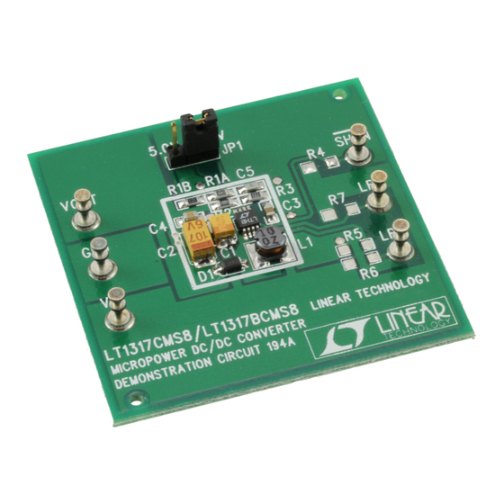
Board Photo
TM
VALUE
1.5V to 3.6V
1.5V to 5.3V
175mA
320mA
140mA
290mA
25µA
125µA
4.8mA
DC194 BP
1
Advertisement
Table of Contents

Related Manuals for Linear LT1317B


Summary of Contents for Linear LT1317B
- Page 1 PC card devices. topologies. The LT1317 and LT1317B are 600kHz PWM DC/DC con- , LTC and LT are registered trademarks of Linear Technology Corporation. verters. Their high operating frequency and small package Burst Mode is a trademark of Linear Technology Corportion.
-
Page 2: Typical Performance Characteristics
DEMO MANUAL DC194 MICROPOWER BOOST REGULATOR TYPICAL PERFORMANCE CHARACTERISTICS LT1317B Efficiency LT1317B Efficiency = 3V = 3.3V LT1317B LT1317B = 3.3V = 5V = 2.4V = 2.4V = 1.6V = 1.6V 1000 1000 LOAD CURRENT (mA) LOAD CURRENT (mA) DC194 G06... -
Page 3: Parts List
QUICK START GUIDE DC194 can regulate a 3.3V output from an input of 1.5V The LT1317/LT1317B can be placed in shutdown mode to 3.6V; it can regulate a 5V output from an input of 1.5V by tying the SHDN terminal to the GND terminal. For to 5.3V. - Page 4 IC; the LT1317 is marked with the supply on the input. code LTHA, whereas the LT1317B is marked with LTHB. In the comments below, “LT1317” will refer to both parts. In With power applied to the DC194, the LT1317 should be cases where their characteristics result in different behav- switching and regulating the output.
-
Page 5: Shut Down Mode
DEMO MANUAL DC194 MICROPOWER BOOST REGULATOR OPERATIO LT1317 will run in this condition. The LT1317 will also operate if this pin is pulled above 1.4V by an external signal. The SHDN pin can be pulled as high as V + 0.3V. AC COUPLED 100mV/DIV The LT1317 is placed in shutdown mode by pulling this pin... - Page 6 DEMO MANUAL DC194 MICROPOWER BOOST REGULATOR OPERATIO voltage. Normally, the high resistance of the ammeter will DESIGN ALTERNATIVES not be present, so its negative effect on efficiency mea- Component Selection surements is misleading. This measurement problem can be avoided by adding a large (1000µF to 10,000µF) bypass The components used for the DC194 represent a compro- capacitor across V between the ammeter and the DC194.
- Page 7 Output Ripple Makes the Loop Compensation Components Trace Appear as Two Traces. = 2.5V, V = 3.3V, LT1317B The components connected to the V pin of the LT1317 (C3, R3 and C5) compensate the control loop of the DC194. The values chosen here are conservative and therefore offer very low output ripple in a small package.
-
Page 8: Low-Battery Detector
1.00M SHDN The second concern in using ceramic capacitors is that LT1317/ 10µF 2.2µF LT1317B many switching regulators benefit from the ESR of the 6.3V 6.3V 332k output capacitor because it introduces a zero in the regulator’s loop gain. This zero may not be effective 6.8nF... - Page 9 DEMO MANUAL DC194 MICROPOWER BOOST REGULATOR OPERATIO BATTLOW 1.00M 0.01µF 118k 1.00M SHDN 86.6k DC194 F07 Figure 7. Here Are Two Applications of the Low-Battery Detector. In (a) It Is Used to Sense the Battery Voltage and Trips when V Falls Below 1.75V.
- Page 10 DEMO MANUAL DC194 MICROPOWER BOOST REGULATOR PCB LAYOUT A D FIL DC194 TSP DC194 TSLK Silkscreen Top Solder Paste Top DC194 TSM DC194 BSM Solder Mask Bottom Solder Mask Top...
- Page 11 Information furnished by Linear Technology Corporation is believed to be accurate and reliable. However, no responsibility is assumed for its use. Linear Technology Corporation makes no represen- tation that the interconnection of its circuits as described herein will not infringe on existing patent rights.
- Page 12 6. FILL UP ALL VIAS WITH SOLDER 7. ALL DIMENSIONS ARE IN INCHES dc194 LT/TP 0299 500 • PRINTED IN USA Linear Technology Corporation 1630 McCarthy Blvd., Milpitas, CA 95035-7417 (408) 432-1900 FAX: (408) 434-0507 www.linear-tech.com © LINEAR TECHNOLOGY CORPORATION 1999...
Need help?
Do you have a question about the LT1317B and is the answer not in the manual?
Questions and answers