Table of Contents
Advertisement
Quick Links
Janitza electronics GmbH
Vor dem Polstück 1
D-35633 Lahnau
Support Tel. +49 6441 9642-22
Fax +49 6441 9642-30
e-mail: info@janitza.com
Internet: http://www.janitza.com
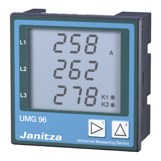
Universal Measuring Device
UMG 96
Operating instructions
Brief instructions see last page
L
L1-N / L1-L2
L2-N / L2-L3
Maximum value
L3-N / L3-L1
S
Minimum
Supply
value
M
M
Mean value
P P rogramming mode
Sum measurement
Phase to phase
Password
Voltage transformer
Current transformer
Output K1
Output K2
Key 2
Key 1
Key 2
Advertisement
Table of Contents

Related Manuals for janitza optec UMG-96


Summary of Contents for janitza optec UMG-96
- Page 1 Password Voltage transformer Current transformer Output K1 Output K2 Key 2 Minimum Supply Key 1 Key 2 value Janitza electronics GmbH Vor dem Polstück 1 D-35633 Lahnau Support Tel. +49 6441 9642-22 Fax +49 6441 9642-30 e-mail: info@janitza.com Internet: http://www.janitza.com...
-
Page 2: Table Of Contents
Table of contents Receipt control Programming mode Key functions Product description Table 1, Measured value indications Intended use Password Hints for the user Current transformer Functional description Programming Hints for Maintenance Voltage transformer Repairs and calibration Programming Front foil Outputs K1 and K2 Waste management Usage as switching output Installation... -
Page 3: Receipt Control
Receipt control In order to ensure a perfect and safe use of the device, a proper transport, expert storage, erection and mounting and careful usage and maintenance are required. When it may be supposed, that a safe operation is no longer possible, the device has to be put out of service and be protected against unintentional putting into service. -
Page 4: Product Description
Product description Intended use The UMG96 is suited for fixed mounting and the measurement of voltage, current, power etc. in low voltage switchgear. The measurement is designed for 3 phase systems with neutral conductor (TN and TT-mains). Measurement and supply voltages (50Hz/60Hz) up to 275VAC against earth and 476VAC phase to phase can be connected directly. -
Page 5: Hints For Maintenance
Hints for Maintenance Before delivery the device is tested in various safety checks and marked with a seal. If the device is opened, these checks must be repeated. Attention! The guarantee is void if the seals are broken. Repairs and calibration Repairs and calibration can only be carried out by the manufacturing. -
Page 6: Installation
Installation Mounting place The UMG96 is suitable for a fixed installation into low and medium voltage switchgear. Any mounting position is possible. Measurement and supply voltage The measurement is laid out for three phase systems with neutral conductor (TN and TT mains). The measure- ment and supply voltages must be connected to the UMG 96 via a separation (switch or power switch) and an overcurrent protection (2-10A) within the building installation.The connection of the measurement and supply voltages is carried out at the back side of the UMG 96 via shock protected spring clamps. -
Page 7: Connection Diagrams
Connection diagrams 10210050ot 10210050ot UMG 96 UMG 96 Hilfsausgang Hilfsausgang Auxiliary Messung Auxiliary Messung Measurement Output Measurement Output Siehe Siehe Typenschild 0,01 .. 5A Typenschild 0,01 .. 5A 2 3 4 5 6 7 8 9 10 11 12 13 14 1 2 3 4 5 6 7 8 9 10 11 12 13 14 L1 L2 L3 N... -
Page 8: Installation And Putting Into Service
Installation and putting into service The installation and putting into service of the UMG96 should be carried out as follows: - Mount the device - Connect measurement and supply voltage Before connection of the measurement and supply voltage to UMG96, please ensure, that the net conditions match the information on type plate. -
Page 9: Check Phase Assignment
Check phase assignment The assignment of the outer conductors to the current transformer is correct, if a current transformer is short circuited on the secondary, and the indicated current in the corresponding phase decreases to 0A at the UMG96. Check current flow Short circuit two current transformers on the secondary. -
Page 10: Removal Of Errors
Removal of errors Fault Reason Removal Display dark. Fuse released. Insert Fuse. Device defective. Send the device to the manufacturer for repair. Measured value cannot The indication has been deleted in Add the required measured value indication to be called up. measured value selection. -
Page 11: Service
- Detailed error description. You can reach us:Monday until Thursday between 07:00 and 15:00 and Friday between 07:00 and 12:00 Janitza electronics GmbH Vor dem Polstück 1 D-35633 Lahnau Support: Tel. (0 64 41) 9642-22 Fax (0 64 41) 9642-30 e-mail: info@janitza.de... -
Page 12: Usage And Display
Usage and display The usage of the UMG 96 is carried out via the keys one and two. Measured values and programming data are indicated on the liquid crystal display. You must distinguish between Indication mode and Programming mode. By entering a password, you can avoid unintentional change of programming data. Indication mode In indication mode you can scroll through the programmed measured value indications by using the keys 1 and 2. -
Page 13: Key Functions
Key functions Indication mode Password Programming mode simultaneous simultaneous Programming Measured menu values Programming Measured menu values Measured Programming Measured menu values values long short Programming Confirm selection menu short number +1 long number -1 short value *10 (dec. point to the right) long value/10 flashing... - Page 14 Table 1, Measured value indications Minimum values Measured values Maximum values L1-N V , meas. value L1-N Voltage L1-N V, meas. value L2-N V , meas. value L2-N Voltage L2-N V, meas. value L3-N V , meas. value L3-N Voltage L3-N V, meas.
- Page 15 Measured values Mean values Max. values (ind) L1 Reactive power L1 Reactive power L1 Reac. power, meas. L2 Reactive power L2 Reactive power L2 Reac. power, meas. L3 Reactive power L3 Reactive power L3 Reac. power, meas. Mean value Max. value (ind) Measured value Sum reactive power Sum reac.
-
Page 16: Password
Password To avoid an unintentional change of programming data, a user pass- word can be entered. If the correct user password is entered, a change into the following programming menus is possible. In delivery condition, no user password is given (000). In this case, the user password is skipped and you reach the current transformer menu immediately. -
Page 17: Voltage Transformer
Voltage transformer Only voltages with a secondary voltage, which is marked on type Primary voltage plate of the UMG 96, can be connected. Type plate Input voltage UMG96 UMG96 L-L (Secondary voltage) 196 .. 275V (Standard version) 400V 98 .. 140V 220V und 200V (Option) 49 .. -
Page 18: Outputs K1 And K2
Outputs K1 and K2 The UMG96 has got two outputs. Each output can either be used as a switching output or pulse output. The presetting for the outputs is: Output 1 = Pulse output for real energy Output 2 = Pulse output for reactive energy Outputs, which are assigned to a energy, energy as a pulse output. -
Page 19: Usage As Switching Output
Usage as switching output Exceeding Limit If a measured value, but not energy, is assigned to the outputs K1 or K2, the output energys as a switching output. The following values for programming are at your disposal: Limit Decimal point Measured value Sign Exceeding / underscoring... -
Page 20: Usage As Pulse Output
Usage as pulse output Pulse valency=100VArh/pulse If real energy is assigned to output K1 or reactive energy to K2, the respective output energys as a pulse output. For each pulse output, a pulse valency can be defined (Wh/pulse, VArh/pulse). The pulses, sampled within one second, are given out with a minimum duration VArh of 50ms and a maximum frequency of 10Hz. -
Page 21: Pulse Valency
Pulse valency The pulse valency is given in Wh per pulse. Pulse valency = Energy per pulse The pulse valency may not be confused with the kW-meter-constant. The kW-meter-constant is given in kW-meter-constant = Rotations per kWh The context between pulse valency and kW-meter- constant can be seen in the following correlations: kW-meter-constant = 1/pulse valency Pulse valency = 1/kW-meter-constant... -
Page 22: Minimum Pulse Width
Minimum pulse width If one of the outputs K1 or K2 is used as pulse output, a programmable minimum pulse width is assigned. The minimum pul- MkWh se width cannot be set separately for the outputs K1 and K2, but is MkVArh valid for both pulse outputs. -
Page 23: Averaging Times (Bimetal Function)
Averaging times (Bimetal function) For the most current and power values, a mean value is built. You can Symbol for mean value program a common averaging time for the current measured values L1, L2, L3 and N , and one for power measured values, real power, apparent power and reactive power is programmable. -
Page 24: Measured Value Rotation
Measured value rotation Rotation time in seconds Once in a second all measured values are calculated and can be shown on the display. For calling up the measured value indications, two methods are available: - The automatic rotating indications of selected measured value indications, in the following called measured value rotation. -
Page 25: Measured Value Selection
Measured value selection In programming menu „measured value selection“, the measured value indications can be selected via the two keys for automatic rota- tion. All listed measured values from table 1 can be called up via the keys 1 and 2, when the device is delivered. The selection for automatic rotation is programmed together with the value selection. -
Page 26: Delete Minimum And Maximum Values
Delete minimum and maximum values In programming mode, the menu „delete minimum and maximum values“ is marked with an arrow up- and downwards. All minimum and maximum values can only be deleted simultaneously. One exception is the maximum value of current mean value. The maximum value of current mean value can be deleted directly in in- dication menu by pressing key 2 for a long time. -
Page 27: Lcd Contrast
LCD contrast The favoured view for the LCD display is from below. This favoured view can be adapted by the user. The contrast setting is possible in steps from 0 to 15. 0 = Very light 15 = Very dark In order to achieve an optimum contrast over the whole temperature range, the inner temperature of the device is measured and the contrast setting is corrected automatically. -
Page 28: Indicating Range And Accuracy
Indicating range and accuracy Quantity Indicating range Measuring range Accuracy Meas. and supply voltage 196 .. 275V Voltage L-N 0 .. 34kV 196 .. 275V +-1,0% rng Voltage L-L 0 .. 60kV 340 .. 476V +-2,0% rng Current 0,00 .. 9,99kA 0,02 .. -
Page 29: Configuration Data
Configuration data Description Display Setting range Presettings Current transformer, primary 1A .. 10,0kA (../5A) 1A .. 2,0kA (../1A) Current transformer, secondary 1A, 5A Voltage transformer, primary Type plate, 196 .. 275V 100V .. 60,0kV 400V Typeplate, 98 .. 140V 100V .. 60,0kV 200V Type plate, 49 .. -
Page 30: Technical Data
Technical data Weight : 250g Calorific value : 2,2MJ (610Wh) Ambient conditions Overvoltage class : CATIII Pollution degree Ambient temperature : -10°C .. +55°C Storage temperature : -20°C .. +70°C Humidity : 15% up to 95% without dew Protection class Front : IP40 according to IEC529 Front with seal (option) -
Page 31: Back Side
Back side +0,8 +0,8 Cut out: 92 x 92 10210060b Side wiew 10210060a Dimensions in mm = Peak value = Minimum value = Supply Page 31... -
Page 32: Brief Instructions
Brief instructions Pressing the keys 1 and 2 for about 1 second, you reach programming mode. If you are in programming mode, you return to indicating mode by pressing keys 1 and 2 for about 1 second. Programming mode Programming of current transformer Select current transformer menu: Press both keys simultaneously for about 1 second.
Need help?
Do you have a question about the optec UMG-96 and is the answer not in the manual?
Questions and answers