Table of Contents
Advertisement
Quick Links
Advertisement
Table of Contents

Related Manuals for Bluebell BC625


Summary of Contents for Bluebell BC625
- Page 1 BC625 Fibre Audio Interface BC625 Operation Guide Ref: BC625-OperationGuide-v2...
- Page 2 Bluebell Opticom Ltd. has taken all possible steps to ensure that the information given here is both correct and complete. In no event can Bluebell Opticom Ltd. accept any liability or responsibility for any loss or damage to the owner of the equipment, any third party, or any equipment which may result from use of this manual or the equipment which it describes.
- Page 3 RoSH and WEEE declaration Bluebell Opticom Ltd. complies with EU RoSH Directive 2002/95/EC, which restricts the use of substances hazardous to humans and their environment in the manufacture of electrical and electronic equipment. The “crossed out wheelie bin” symbol on the enclosures and represented above is there to remind users of the obligation of selective collection of waste.
-
Page 4: Table Of Contents
Table of Contents Overview ...................... 5 Introduction ...............................5 Physical formats .............................5 Power requirements ..........................5 BC625 connections ..................6 System block diagram ................... 8 Configuration and setup options ....................9 Appendix ...................... 9 Specifications – BC625 ......................10 Optical wavelengths ........................11 BC625-OperationGuide-v2... -
Page 5: Overview
Thank you for purchasing this Bluebell Opticom professional broadcast video product. If you are new to Bluebell products, or to the subject of transmitting audio or other types of signals over fibre links, please take the time to read through this document before putting the BC625 to use. -
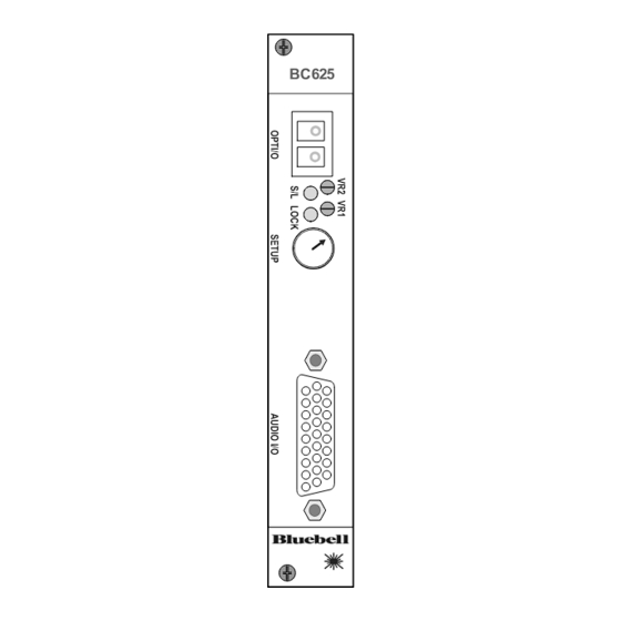
Page 6: Bc625 Connections
BC625 connections BC625 1. AUDIO I/O – all audio connections are made via the hi-density 26-pin female Dsub connector. All audio inputs and outputs are electronically balanced and at line level, nominally 0 dBu (0.775 V Wire the mating Dsub connector according to the pinout listed below:... - Page 7 2. OPTICAL I/O - SFP dual fibre connector. The connector is mounted on a removable cartridge. The BC625 uses single-mode fibre as standard, at a wavelength of 1310 nm; alternative CWDM wavelengths or multi-mode operation are available if specified at the time of order.
-
Page 8: System Block Diagram
The analogue audio outputs are electronically balanced, and can supply a maximum level of +18 dBu (ref 1 mW into 600 ohms). Note that overall gain throughout the system – transmitter > optical fibre > receiver – is unity (0 dB). BC625-OperationGuide-v2... -
Page 9: Configuration And Setup Options
Configuration and setup options The BC625 has only one setup option which may need to be altered by the user. This controls the audio signal level relationship between analogue and digital domains. The jumper, LK1, is located at the rear of the left-hand PCB, as the module is viewed from the rear. -
Page 10: Appendix
Appendix Specifications – BC625 Analogue audio Inputs (4) Input impedance 24 kohm (balanced) Max. input level +24 dBu (ref 1mW into 600 ohms) Noise < -90 dB pk-pk weighted full scale Frequency response 20 Hz – 20 kHz ±0.5 dB... -
Page 11: Optical Wavelengths
Single mode, single channel CWDM SFP transmitter, 1530nm DTR/S/SFP/CWDM/55 Single mode, single channel CWDM SFP transmitter, 1550nm DTR/S/SFP/CWDM/57 Single mode, single channel CWDM SFP transmitter, 1570nm DTR/S/SFP/CWDM/59 Single mode, single channel CWDM SFP transmitter, 1590nm DTR/S/SFP/CWDM/61 Single mode, single channel CWDM SFP transmitter, 1610nm BC625-OperationGuide-v2...
Need help?
Do you have a question about the BC625 and is the answer not in the manual?
Questions and answers