
Related Manuals for PASI GEA24


Summary of Contents for PASI GEA24
- Page 1 PASI User Manual Seismograph GEA24 P.A.S.I srl – via Galliari 5/E – 10125 TORINO – Italy Tel. +39 011 650.70.33 – Fax +39 011 658.646 - E-mail sales@pasisrl.it www.pasisrl.it...
-
Page 3: Table Of Contents
Hardware Connection ....................13 Power supply ....................... 14 Full description of graphical interface and functionality ........15 Homepage ......................15 6.1.1 Connecting the instrument Gea24 to the PC ..........16 6.1.2 Setting the acquisition configuration template ......... 17 System Configuration..................17 6.2.1 Configuration of linear measurement unit .......... - Page 4 6.4.1 Geophone noise monitoring ..............34 6.4.2 Trigger Window ..................36 6.4.3 The "Acquisition in progress" window ............. 38 6.4.4 Stacking ..................... 38 6.4.5 Display of acquired data ................39 6.4.6 Applying filters ..................43 6.4.7 Stacking Configuration ................43 Data Backup .....................
- Page 5 Table of Contents GEA24 SEISMOGRAPH...
-
Page 6: Important Notice
P.A.S.I. products have not been designed to be used in any way or applications other than those mentioned. This guide refers to “GEA24” SW version 2.0.2, Firmware version 2.5, HW library version 2.6. Torino, ITALIA 2016... - Page 7 Important Notice GEA24 SEISMOGRAPH...
-
Page 8: Warranty And Safety Instructions
Faultless and safe operation of the device can be guaranteed only if the transport, storage, handling and operation of the device is appropriate. To prevent damage, use only original accessories or approved by PASI srl. The box is waterproof only if closed. When a suitable location has been selected for the seismograph, it must be ensured that no water can get into the device under any conditions. - Page 9 Warranty and safety instructions GEA24 SEISMOGRAPH...
-
Page 10: Introduction
4. Introduction The seismograph GEA24 is a device designed and assembled by P.A.S.I. srl, a leading company in Italy in the production of instruments for geology and geophysics. This guide details the technical specifications and how to use the device. Please follow these guidelines. - Page 11 Introduction GEA24 SEISMOGRAPH...
-
Page 12: How To Use
- USB Stick Gea24 containing manual and software - Registration card You can connect Gea24 to a laptop or tablet PC via USB cable; the Gea24 is also powered by the PC itself, so you do not need an external 12V battery. -
Page 13: Hardware Connection
How to use IGURE CONNECTED TO A Hardware Connection Gea24 can be placed either at the ends or in the center of the spreading; the patterns reported below simply represent the most common configuration. GEA24 SEISMOGRAPH... -
Page 14: Power Supply
In addition to the seismic cables, to become "active" GEA24 must be connected to a trigger or starter geophone using the supplied special connector. Power supply As indicated in Par.1.2, Gea24 is powered by the PC via the USB port; an external 12V battery is not necessary. -
Page 15: Full Description Of Graphical Interface And Functionality
6. Full description of graphical interface and functionality Homepage The homepage is the starting page of the Gea24 program which allows you to control all operations: system parameter configuration (button 2, section 6.2) configuration of acquisition parameters and geophones (key 4, paragraph 6.3);... -
Page 16: Connecting The Instrument Gea24 To The Pc
GUI together with the hardware serial number. If you connect two Gea24 tools there will be two images shown on the GUI with two serial numbers. Tool number 1 will be the one with the lowest serial number, while tool number 2 will be the one with the highest serial number. -
Page 17: Setting The Acquisition Configuration Template
Full description of graphical interface and functionality NOTE 2: After updating the Gea24 software on the PC, its first connection to the USB might require a few seconds while the system is detected, as an update of the firmware on Gea24 tool might be necessary. -
Page 18: Configuring Geophones Sensitivity Unit Of Measure
ABLE 6.2.3 Configuring SEG2 preferences The window allows you to enter your preferences for the string proposed by the Gea24 program as a default for the name SEG2 file storage of the acquired data. The following information will assist the operator with the name of the file. -
Page 19: Configuration Of The Seg2 File Directory
The configuration function for the SEG2 file folder is only for Gea24 system with external Configuring acquisition parameters To open the acquisition configuration window press "Acquisition Config"... -
Page 20: Configuration Window Of The Lines (Lines Configurations)
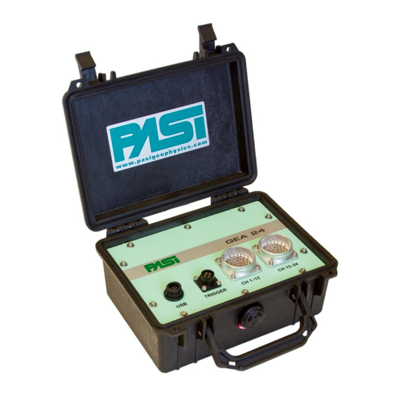
Above you can see the line attached to the Gea24 left connector, the geophones are numbered from 1 to 12 as indicated on the front panel of the instrument. Below you can see the line attached to the Gea24 right connector, the geophones are numbered from 13 to 24 as indicated on the front panel of the instrument. - Page 21 By selecting the checkbox "Polarity inversion 1-12" you can invert the polarity of the signals acquired by Gea24 system on the line on the left before processing and saving them. Similarly by selecting the checkbox " Polarity inversion 12-24" you can invert the...
- Page 22 Gea24 system on the right line before processing and saving them. Via the checkbox "Select 1-12" you can enable or disable all the geophones of the line to the left, likewise via the checkbox "Select 12-24" you can enable or disable all the geophones of the line to the right.
-
Page 23: Data Collection Configuration Window (Acquisition Configuration)
Full description of graphical interface and functionality The maximum frequency values in the tables 3 and 4 are valid for a single commanded Gea24 instrument. In the case of acquisitions made with two Gea24 instruments connected simultaneously, the maximum configurable frequency sampling will be the lower between the two Gea24 instruments considered separately. - Page 24 5 – “A ” IGURE CTIVE ACQUISITION CONFIGURATION WINDOW The following describe the parameters to include in the configuration window. Sampling: through the drop-down menu the sampling frequency must be configured (or the corresponding sampling period) of the signal. The number of configurable values and the maximum frequency are dependent on the number and position of the geophones that have been enabled in the configuration phase of the lines, as described in paragraph 6.3.1.
- Page 25 Acquire trigger: the trigger signal will be acquired displayed and saved by ticking the checkbox, otherwise it will not be acquired, displayed and saved. High Pass Filter, Notch Filter (Suppress harmonics, if checkbox selected), Low Pass Filter: You can configure the filters that will be applied to the acquired signal. GEA24 SEISMOGRAPH...
- Page 26 High pass filter None 10 Hz 20 Hz 30Hz 40 Hz 50 Hz 70 Hz 100 Hz 150 Hz 200 Hz 300 Hz 400 Hz 7 - H ABLE IGH PASS FILTER Notch filter None 50 Hz 60 Hz 8 - N ABLE OTCH FILTER Low-pass filer...
- Page 27 If this time is less than the sum of the acquisition time plus the data collection time, on the PC the next acquisition will start immediately following. Repetitions: number of successive acquisitions that have to be made automatically. GEA24 SEISMOGRAPH...
- Page 28 High Pass Filter, Notch Filter (Harmonics Suppression if checkbox selected), Low Pass Filter: You can configure the filters that will be applied to the acquired signal. 6.3.2.3 Non multiple passive acquisition configuration window The configuration window for the "Passive" mode and non-multiple configuration is shown in Figure 7.
-
Page 29: Geophone Configuration Window
With this configuration there are 18 geophones in the table, since only the enabled geophones for collecting measurements are reported. The table has the following columns. GEA24 SEISMOGRAPH... -
Page 30: Viewing And Changing The Configuration Of A Single Geophone (Only For Gea24 Embedded Pc)
6.3.4 Viewing and changing the configuration of a single geophone (only for GEA24 embedded PC) This window is only present on the Gea24 system with embedded PC, and is used when entering the parameters of the geophones. Figure 9 is an example of the window. - Page 31 (see section 6.3.5). GEA24 SEISMOGRAPH...
-
Page 32: Changing Parameters On All Geophones
6.3.4.1 Selecting a geophone, the source or the trigger The item you select (geophone, source or trigger) for which you want to display data can be done in two ways: press one of the specific selection keys of a geophone (source, trigger, previous geophone, next geophone);... - Page 33 Apply: the button must be pressed to apply the chosen algorithm with the set parameters so that you can calculate the values and assign them to the enabled geophones. GEA24 SEISMOGRAPH...
-
Page 34: Saving A Configuration
6.3.6 Saving a Configuration Saving a Configuration allows you to store all the information contained in a configuration, hence the set of parameters entered in the three windows: lines configuration the Acquisition configuration and Configuration of geophones. Each saved configuration can be identified and retrieved via the name the operator gave it. To save a configuration use the save button in any of the three windows of the configuration parameter input. - Page 35 The checkbox labelled "High Gain all geos" allows you to select the high gain for all geophones simultaneously, or deselect it for all geophones. GEA24 SEISMOGRAPH...
-
Page 36: Trigger Window
The Gea24 system will acquire signals from the geophones, will compare them with a threshold and return to the noise monitoring window by configuring each individual geophone with high gain if the acquired signal is below the threshold used, or with a low gain if the signal acquired is located above the threshold. - Page 37 Main - Exits the window of early acquisition and goes back to the homepage, in this case, the acquisition is not made and you will have to repeat the procedure from the beginning (New acquisition -> Noise Monitor -> Acquisition). GEA24 SEISMOGRAPH...
-
Page 38: The "Acquisition In Progress" Window
In the case of an non-multiple acquisition, the Gea24 system will carry out acquisition in a continuous way for the planned duration of the acquisition configuration, whereas in... -
Page 39: Display Of Acquired Data
To end the acquisition operation, the operator can press the main button, and in this case the data acquired up to that time will be deleted and the system will return to the Gea24 homepage. 6.4.5 Display of acquired data After the acquisition is completed, the Gea24 will proceed to collect the acquired signals and will apply any configured filters. - Page 40 Across the top are the ID numbers of the physical geophones (Trg identifies the signal acquired from the Trigger). The letter "P" indicates that the signal is shown with the polarity as it has been acquired. If the signal is inverted from the "View / Filter" window the indication becomes "- P"...
- Page 41 3 geophones displayed. Amplitude range: full scale used on the amplitude of the individual signals, allows you to select the full scale that you want to apply to all signals displayed. The operator can choose from the following: GEA24 SEISMOGRAPH...
- Page 42 Global - The signals obtained are presented with the same full scale value, this is relative to the maximum amplitude value measured on all acquired signals. This view will allow you to have a visual reference of the attenuation of the signals received on the different geophones. Through a special checkbox, the operator can choose whether to include the signal of the trigger from the calculation of the maximum amplitude: if you want to exclude the trigger signal, the latter will have its own full scale that will...
-
Page 43: Applying Filters
To avoid stacking on a geophone that is considered satisfactory, the corresponding checkbox will have to be selected, otherwise stacking will be carried out on the geophones that have not been selected. GEA24 SEISMOGRAPH... -
Page 44: Data Backup
15 - S IGURE TACKING INDOW ONFIGURATION To carry out stacking on unselected geophones the OK button must be pressed. You will return to the "Automatic trigger" window and a new acquisition procedure will be carried out (see paragraph 6.4.2.1). The window also contains the following command button: Back - Exits the "stacking configuration"... -
Page 45: Viewing And Entering Seg2 Parameters
The "Configuration SEG2 Parameters" window opens also when carrying out a passive acquisition immediately after the geophone noise monitoring window. The window includes: A drop-down menu containing a list of SEG2 standard parameters that can be entered by the operator; GEA24 SEISMOGRAPH... -
Page 46: Entering The Name Of The Seg2 File
In the window some SEG2 parameters are present for the acquisition automatically filled by Gea24 (in normal characters, cannot be deleted or changed by the operator) plus some optional SEG2 parameters (in bold characters, can be deleted or set at will, the operator provides the value). -
Page 47: Data And Configuration File Management/Managing Configuration And Data Files
Full description of graphical interface and functionality Pressing the "OK" button will allow the Gea24 system to save the data to the control PC’s hard disk. Data and Configuration File Management/managing configuration and data files The button “Manage file” on the homepage (see Figure 3 in Section 6.1) allows you to enter the "File Manager"... -
Page 48: Eliminating The Configuration Template
Exporting data files (only for embedded PC) You can export the data files of SEG2 stored on Gea24 PC memory to a USB memory stick. When the system is on the homepage, insert a USB memory stick or into the USB port located on the front of Gea24, the system will automatically detect the key and will open the "Input / Output Management"... -
Page 49: Multiple Passive Acquisitions
Go to the homepage of the Gea24 program and insert the USB memory stick into a USB port on the control PC (if Gea24 system with external PC) or into the USB port on the front of Gea24 (if Gea24 system with embedded PC). -
Page 50: Recovery After Unexpected Situations
Gea24 at the restart after the abnormal shutdown occurred: If the system detects the presence of acquisition data in the PC or in the Gea24 embedded PC system that has not yet been saved as SEG2 files, it will be recovered. -
Page 51: Active Acquisition With Stacking
The data you collected is saved as temporary files at the end of each stacking acquisition. This means that in the event of a shutdown of the Gea24 system, the data can be recovered with a possible loss of only the data acquired in the last stacking shot/strike if the shutdown occurred while Gea24 was acquiring the data or it was saving it to a temporary file. -
Page 52: Continuous Passive Acquisition
Gea24 file system even if an unexpected shutdown occurs during acquisition. This means that in the event of a shutdown of the Gea24 system, the data can be recovered with a possible loss of only the last data acquired, if the shutdown occurred while Gea24 was acquiring the data or it was saving it to a temporary file. - Page 53 The operator will then be informed that the data has been successfully saved. If the operator had not required storage of the global multiple acquisition files the Gea24 system will not have to perform any data recovery operation.
-
Page 54: Technical Specifications
Appendix A Technical Specifications... -
Page 55: How To Place The Piezoelectric Shock Sensor
Appendix B Appendix B How to place the piezoelectric shock sensor GEA24 SEISMOGRAPH... -
Page 56: Trigger Connector
Appendix C Trigger connector 17 - T IGURE RIGGER CONNECTOR... -
Page 57: Connection Schemes
Appendix D Appendix D Connection schemes 48 Channel seismograph – 12 Channels cables GEA24 SEISMOGRAPH... -
Page 58: Channel Seismograph - 24 Channels Cables
48 Channel seismograph – 24 Channels cables... -
Page 59: Line Connections
Appendix D Line Connections GEA24 SEISMOGRAPH...
Need help?
Do you have a question about the GEA24 and is the answer not in the manual?
Questions and answers