
Related Manuals for Mitsubishi FR-HAL-0.4K


Summary of Contents for Mitsubishi FR-HAL-0.4K
- Page 1 三菱汎用インバータ INVERTER 取扱説明書 Instruction Manual AC リアクトル AC REACTOR FR-HAL-0.4K 〜 110K FR-HAL-H0.4K 〜 H560K...
- Page 2 このたびは、三菱汎用インバータオプションをご採用いただき、誠にありがとうございます。 この取扱説明書は、ご使用いただく場合の取り扱い、留意点について述べてあります。誤った取り扱い は思わぬ不具合を引き起こしますので、ご使用前に必ずこの取扱説明書を一読され、正しくご使用くだ さいますようお願いいたします。 なお、本取扱説明書は、ご使用になるお客様の手元に届くようご配慮をお願いいたします。 安全上の注意 据付、運転、保守・点検の前に必ずこの取扱説明書とその付属書類をすべて熟読し、正しくご使用く ださい。機器の知識、安全の情報そして注意事項のすべてについて習熟してからご使用ください。 この取扱説明書では、安全注意事項のランクを「危険」 、「注意」として区分してあります。 取扱いを誤った場合に、 危険な状況が起こりえて、 死亡または重傷を受ける可能性が 危険 想定される場合。 取扱いを誤った場合に、 危険な状況が起こりえて、 中程度の傷害や軽傷を受ける可能 注意 性が想定される場合および物的損害だけの発生が想定される場合。 なお、 注意 に記載した事項でも、状況によっては重大な結果に結びつく可能性があります。いず れも重要な内容を記載していますので必ず守ってください。 3.傷害防止のために 安全にお使いいただくために 注 意 1.感電防止のために ●各端子には取扱説明書に決められた電圧以外 危 険 は印加しないでください。破裂・破損などの 原因になります。 ●通電中および運転中はオプションの端子台カ ●端子接続を間違えないでください。破裂・破 バーを開けないでください。感電の原因とな 損などの原因になります。 ります。 ●極性(+、−)を間違えないでください。破 ●オプションの端子台カバーをはずしての運転...
- Page 3 4.諸注意事項 (5) 一般的注意 次の注意事項についても十分留意ください。取り 本取扱説明書に記載されている全ての図解は、 扱いを誤った場合には思わぬ故障・けが・感電な 細部を説明するためにカバーまたは安全のた どの原因となることがあります。 めの遮断物を取りはずした状態で描かれてい る場合がありますので、 運転するときは必ず規 (1) 運搬・据え付けについて 定どおりのカバーや遮断物を元どおりに戻し、 注 意 取扱説明書に従って運転してください。 ●製品の重さに応じて正しい方法で運搬してく ださい。けがの原因になります。 ●損傷、部品がかけているオプションを据え付 け、運転しないでください。 ●製品の上に乗ったり重いものを載せないでく ださい。 ●取り付け方向は必ずお守りください。 ●オプション内部にねじ・金属片などの導電性 異物や油などの可燃性異物が混入しないよう にしてください。 ●本オプションは精密機器ですので、落下させ たり、強い衝撃を与えないようにしてくださ い。 ● 下記の環境条件でご使用ください。製品故障 の原因になります。 −10℃〜+50℃ 周囲温度 (凍結のないこと) 90%RH以下 周囲湿度 (結露のないこと) 環 保存温度 −20℃〜+65℃ *1 屋内(腐食性ガス、引火性ガ...
-
Page 4: Table Of Contents
目 次 製品の確認 ....................2 据 付 け ....................2 配 線 ....................3 電線サイズと圧着端子................4 仕 様 ....................5 外形寸法図 ....................6... -
Page 5: 製品の確認
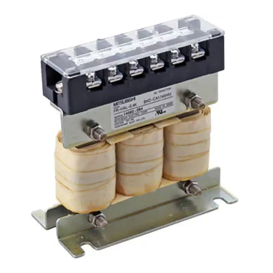
製品の確認 製品の確認 (1) 梱包箱からオプションユニットを取り出し、ご注文どおりの製品であ るか、また損傷がないかの確認をしてください。 MITSUBISHI REACTOR MODEL XXXXXXXXXXXX FR‑HAL‑□□K SERIAL MITSUBISHI ELECTRIC CORP. FR‑HAL‑ H □□K 適用モータ容量(kW) 記号 適用電源電圧 なし 200Vクラス 400Vクラス (2) 同梱品がすべて揃っていることを確認してください。 端子台カバー ....1 個 AC リアクトル (FR-HAL) (200V クラス 15K 以下、 取扱説明書....1 部 ........1 個 400V クラス 55K 以下 ) *... -
Page 6: 配 線
配 線 配 線 下記の結線図に従ってリアクトルとインバータ間を接続してください。AC リアクトルはインバータの入力側に接続します。 インバータ 電源 < 3 相電源> (1) 2 台以上のインバータに AC リアクトルを使用する場合には、下図のよ うに、必ずインバータ 1 台ごとに AC リアクトルを接続してください。 まとめて1台のリアクトルで使用した場合には、全部のインバータ が運転されないと、十分な力率改善効果が得られません。 FR‑HAL 電 源 インバータ FR‑HAL インバータ (2) 適用するモータ容量に合わせて選定してください。 (インバータ容量が モータ容量よりも大きい場合も、モータ容量に合わせて選定します。 ) 0.4kW 未満のモータの場合は、0.4kW 用を選定します。 注 意 1. 配線時に端子台の端子カバーを取り外してから配線作業を行って ください。配線終了後、端子カバーを取り付けてください。 2. 通電中および運転中の配線作業は行わないでください。 3. -
Page 7: 電線サイズと圧着端子
電線サイズと圧着端子 電線サイズと圧着端子 (1) 200V クラス HIV 電線 適用インバータ 端子 圧着 形名 容量 サイズ 端子 サイズ(mm ) FR-HAL-0.4K 0.4K FR-HAL-0.75K 0.75K FR-HAL-1.5K 1.5K FR-HAL-2.2K 2.2K FR-HAL-3.7K 3.7K 5.5-4 FR-HAL-5.5K 5.5K 5.5-4 FR-HAL-7.5K 7.5K 14-5 FR-HAL-11K 14-6 FR-HAL-15K 22-6 FR-HAL-18.5K 18.5K 38-8... -
Page 8: 仕 様
仕 様 HIV 電線 適用インバータ 端子 圧着 形名 容量 サイズ 端子 サイズ(mm ) FR-HAL-H45K 38-8 FR-HAL-H55K 60-8 FR-HAL-H75K 60-10 FR-HAL-H110K 60-12 FR-HAL-H110K 110K 80-12 FR-HAL-H185K 132K 100-12 FR-HAL-H185K 160K 150-12 FR-HAL-H185K 185K 150-12 FR-HAL-H280K 220K 100-12 2 × 100 FR-HAL-H280K 250K 100-12 2 ×... -
Page 9: 外形寸法図
R X S Y T Z 4‑d用取付穴 (手前右側、 MAX D ワニス除去)*1 ±2 MAX W *3 *1 接地配線する場合に使用してください。 形名 D 質量 (kg) * 2 FR-HAL-0.4K FR-HAL-0.75K FR-HAL-1.5K FR-HAL-2.2K *2 FR-HAL-3.7K *2 FR-HAL-5.5K *2 (単位:mm) * 2 Max 寸法です。 (入出力線の曲げにより寸法が変化します。 ) * 3 FR-HAL-0.4K 〜 1.5K は W ± 2 となります。... - Page 10 外形寸法図 ●FR-HAL-7.5K〜15K 端子配列 R X S Y T Z 4‑d用取付穴(手前右側、ワニス除去)*1 MAX D ±2 ±2 *1 接地配線する場合に使用してください。 形名 D 質量(kg) * 2 FR-HAL-7.5K FR-HAL-11K FR-HAL-15K (単位:mm) * 2 Max 寸法です。 (入出力線の曲げにより寸法が変化します。 )...
- Page 11 外形寸法図 ●FR-HAL-18.5K〜55K MAX W *3 ±2 4‑d用取付穴 MAX D (手前右側、 ワニス除去)*1 *1 接地配線する場合に使用してください。 形名 D 質量(kg) * 2 FR-HAL-18.5K FR-HAL-22K *2 FR-HAL-30K *2 FR-HAL-37K 12.9 *2 FR-HAL-45K 16.4 *2 FR-HAL-55K 17.4 *2 (単位:mm) * 2 Max 寸法です。 (入出力線の曲げにより寸法が変化します。 ) * 3 FR-HAL-18.5K は W ± 2 となります。...
- Page 12 外形寸法図 ●FR-HAL-75K、110K MAX D 6−端子M12ボルト用 (R) (S) (T) (X) (Y) (Z) (E) 接地端子 W2 1 D2 M8ネジ*1 W1 2 D1 2 MAX W 4‑d用取付穴 *1 接地配線する場合に使用してください。 質量 形名 W W1 W2 H1 D * 2 * 2 (kg) FR-HAL-75K 240 240 150 210± 5 3.2 215.5 127 109 63± 2.5 M8 FR-HAL-110K 330 270 170 325±...
- Page 13 外形寸法図 (2) 400V クラス ●FR-HAL-H0.4K〜H3.7K ワニス除去(表、裏)*1 端子配列 R X S Y T Z 4‑d用取付穴 (φ5溝穴) MAX D 端子台 ±0.5 ●FR-HAL-H5.5K〜H15K ワニス除去(表、裏)*1 端子配列 R X S Y T Z 4‑d用取付穴 (φ6溝穴) MAX D 端子台(2ヶ) ±0.5 * 1 接地配線する場合に使用してください。 形名 W D 質量(kg) *...
- Page 14 外形寸法図 ●FR-HAL-H18.5K〜H37K ワニス除去(表、裏)*1 端子配列 R X S Y T Z 4‑d用取付穴 (φ6溝穴) MAX D 端子台(2ヶ) ±0.5 ●FR-HAL-H45K、H55K ワニス除去(表、裏)*1 端子配列 R X S Y T Z 4‑d用取付穴 (φ8溝穴) MAX D 端子台(2ヶ) ±0.5 * 1 接地配線する場合に使用してください。 形名 D 質量(kg) * 2 FR-HAL-H18.5K FR-HAL-H22K FR-HAL-H30K FR-HAL-H37K 12.5 FR-HAL-H45K...
- Page 15 外形寸法図 ●FR-HAL-H75K 6−端子M10ボルト用 R 接地端子 W1±1 M8ネジ*1 W±2 D1±2 MAX W2 MAX D 4−d用取付穴 * 1 接地配線する場合に使用してください。 形名 W2 D 質量(kg) * 2 * 2 FR-HAL-H75K 210.5 (単位:mm) * 2 Max 寸法です。 (入出力線の曲げにより寸法が変化します。 )...
- Page 16 外形寸法図 ●FR-HAL-H110K〜H355K MAX D 4‑φ24穴 6−端子S1ボルト用 R 接地端子 W1±1 M8ネジ*1 W±2 D1±2 4−d用取付穴 MAX W2 * 1 接地配線する場合に使用してください。 質量 D 形名 D1 D2 (kg) * 2 * 2 FR-HAL-H110K 240 240 150 225± 5 3.2 220 117 99 63± 2.5 M8 M12 28 FR-HAL-H185K 270 330 170 325±...
- Page 17 外形寸法図 ●FR-HAL-H560K 24‑φ15穴 MAX 635 *2 (R) (S) (T) (X) ( Y) ( Z) (R) (X) (S) (Y) (T) (Z) 接地端子 M8ネジ*1 300±1 345±10 4−M12用取付穴 450±2 395±10 * 1 接地配線する場合に使用してください。 形名 質量(kg) FR-HAL-H560K (単位:mm) * 2 Max 寸法です。 (入出力線の曲げにより寸法が変化します。 )...
- Page 18 Thank you for choosing this Mitsubishi Inverter option. This instruction manual gives handling information and precautions for use of this equipment. Incorrect handling might cause an unexpected fault. Before using the equipment, please read this manual carefully to use the equipment to its optimum.
- Page 19 4. Additional Instructions 4) Disposal Also note the following points to prevent an CAUTION accidental failure, injury, electric shock, etc. Assumes that incorrect handling may cause • Treat as industrial waste. an accidental failure, injury, electric shock, etc. (5) General instruction 1) Transportation and installation All illustrations given in this manual may CAUTION...
- Page 20 Contents Product Checking................2 Installation ..................2 Wiring ....................3 Cable Size and Crimping Terminal ..........4 Specifications .................. 5 Outline Dimension Drawings ............6...
-
Page 21: Product Checking
(1) Unpack the option unit, and ensure that the product received is as you ordered and it is intact. MITSUBISHI REACTOR MODEL FR-HAL- XXXXXXXXXXXX SERIAL MITSUBISHI ELECTRIC CORP. FR-HAL- H Applied motor capacity (kW) Symbol Applied Power Supply Voltage 200V class None 400V class (2) Make sure that the package includes all accessories. -
Page 22: Wiring
Wiring Wiring Connect the reactor and inverter according to the connection diagram below. Connect the AC reactor on the input side of the inverter. <Three-phase power supply> Inverter Power supply (1) When using the AC reactor with two or more inverters, always connect one AC reactor to each inverter as shown below. -
Page 23: Cable Size And Crimping Terminal
Cable Size and Crimping Terminal Cable Size and Crimping Terminal (1) 200V class HIV Cable Size Applicable Terminal Type Crimping Terminal Inverter Capacity Screw Size FR-H L-0.4K 0.4K FR-H L-0.75K 0.75K FR-H L-1.5K 1.5K FR-H L-2.2K 2.2K FR-H L-3.7K 3.7K 5.5-4 FR-H L-5.5K... -
Page 24: Specifications
Specifications HIV Cable Size Applicable Terminal Crimping Type Inverter Capacity Screw Size Terminal FR-H L-H55K 60-8 H75K 60-10 FR-H FR-H L-H110K 60-12 FR-H L-H110K 110K 80-12 FR-H L-H185K 132K 100-12 FR-H L-H185K 160K 150-12 185K 150-12 FR-H L-H185K 2 × 100 FR-H L-H280K 220K... -
Page 25: Outline Dimension Drawings
*1 Use this portion to wire an earthing cable. Type Mass (kg) FR-HAL-0.4K FR-HAL-0.75K FR-HAL-1.5K FR-HAL-2.2K FR-HAL-3.7K FR-HAL-5.5K (Unit: mm) *2 Maximum size (The size changes according to the bending of the input and output cable.) *3 W ± 2 for the FR-HAL-0.4K to 1.5K... - Page 26 Outline Dimension Drawings FR-HAL-7.5K to 15K • Terminal layout R X S Y T Z Installation hole for 4-d (near right side, varnish remove) *1 MAX D *1 Use this portion to wire an earthing cable. Type Mass (kg) FR-HAL-7.5K FR-HAL-11K FR-HAL-15K (Unit: mm)
- Page 27 Outline Dimension Drawings FR-HAL-18.5K to 55K • MAX W *3 Installation hole for MAX D 4-d (near right side, varnish remove) *1 *1 Use this portion to wire an earthing cable. Type Mass (kg) FR-HAL-18.5K FR-HAL-22K FR-HAL-30K FR-HAL-37K 12.9 FR-HAL-45K 16.4 FR-HAL-55K 17.4...
- Page 28 Outline Dimension Drawings FR-HAL-75K, 110K • MAX D For 6-terminal M12 bolt (R) (S) (T) (X) (Y) (Z) (E) W2 1 Earth terminal W1 2 D1 2 M8 screw *1 MAX W Installation hole for 4-d *1 Use this portion to wire an earthing cable. Mass Type W *2...
- Page 29 Outline Dimension Drawings (2) 400V Class FR-HAL-H0.4K to H3.7K • Varnish removal (front, rear) *1 Terminal layout R X S Y T Z Installation hole for 4-d ( 5 groove) MAX D Terminal block FR-HAL-H5.5K to H15K • Varnish removal (front, rear) *1 Terminal layout R X S...
- Page 30 Outline Dimension Drawings FR-HAL-H18.5K to H37K • Varnish removal (front, rear) *1 Terminal layout R X S Y T Z Installation hole for 4-d groove) MAX D Terminal block (2) FR-HAL-H45K,H55K • Varnish removal (front, rear) *1 Terminal layout R X S Y T Z Installation hole for 4-d ( 8 groove)
- Page 31 Outline Dimension Drawings FR-HAL-H75K • For 6-terminal M10 bolt Earth terminal M8 screw *1 MAX W2 MAX D Installation hole for 4-d *1 Use this portion to wire an earthing cable. Type Mass (kg) 210.5 FR-HAL-H75K (Unit: mm) *2 Maximum size (The size changes according to the bending of the input and output cable.)
- Page 32 Outline Dimension Drawings FR-HAL-H110K to H355K • MAX D Installation hole For 6-terminal S1 bolt for 4- 24 Earth terminal M8 screw *1 D1 2 Installation hole MAX W2 for 4-d *1 Use this portion to wire an earthing cable. S1 Mass Type D1 D2...
- Page 33 Outline Dimension Drawings FR-HAL-H560K • Installation hole for 24- 15 MAX 635 *2 (R) (S) (T) (X) (Y) (Z) Earth terminal M8 screw *1 345 10 Installation hole 300 1 for 4-M12 450 2 395 10 *1 Use this portion to wire an earthing cable. Type Mass (kg) FR-HAL-H560K...
- Page 34 MEMO...
- Page 35 MEMO...
- Page 36 IB( 名 )-0600184-A 初版印刷 2004 年 8 月 IB( 名 )-0600184-B 追加 FR-HAL-H75K 2004 年 11 月 IB( 名 )-0600184-C 追加 ・FR-HAL-0.4K 〜 55K ・電線サイズと圧着端子 2005 年 5 月 IB( 名 )-0600184-D 追加 ・FR-HAL-75K 〜 110K ・FR-HAL-H110K 〜 H560K Print Date ※ Manual Number Revision Mar.,2004...
Need help?
Do you have a question about the FR-HAL-0.4K and is the answer not in the manual?
Questions and answers