Advertisement
Quick Installation Guide
Version 1.0
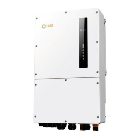
S6-EH3P(30-50)K-H-ND
S6-EH3P(15-30)K-H-LV-ND
Ginlong Technologies Co., Ltd.
Note:
Quick installation is for reference only.
Read the instructions carefully before installing and using
the product.
For access to the manual please scan
the QR code below or you can go the URL
https://www.ginlong.com/global/
service.html
After entering the page, you can click "
icon to change to preferred language.
1
Bottom of the Inverter
Some models may have a different number of DC inputs,
please refer to datasheet/nameplate/actual product.
Smart Port
Communication
Data Logging
Stick (Optional)
DC Switch
PV Input
Data
2
Installation Clearance
Minimum clearance is required.
≥500mm
≥500mm
≥1000mm
3
Mounting Hole Size
Drill holes for the mounting screws based on the hole diameter
of the mounting bracket using a precision drill.
"
Manual Download
4
Mounting the Inverter
AC Backup Port
The steps to mount the inverter are listed below:
AC Grid Port
1.Select the mounting height of the bracket and mark the mounting
holes. For brick walls, the position of the holes should be suitable
for the expansion bolts.
2.Lift up the inverter (be careful to avoid body strain), and align
the back bracket on the inverter with the convex section of the
mounting bracket. Hang the inverter on the mounting bracket
and make sure the inverter is secure.
Battery Input
Install vertically (+/- 5°) or tilted backward (≤15°).
≥500mm
Don't mount inverter on the tilted forward wall.
Don't mount inverter on the horizontal.
unit:mm
Advertisement
Table of Contents

Subscribe to Our Youtube Channel
Summary of Contents for SOLIS S6-EH3PK-H-ND Series
- Page 1 Mounting Hole Size Note: Quick installation is for reference only. Read the instructions carefully before installing and using Drill holes for the mounting screws based on the hole diameter the product. of the mounting bracket using a precision drill. For access to the manual please scan unit:mm the QR code below or you can go the URL https://www.ginlong.com/global/...
-
Page 2: External Ground Connection
External Ground Connection Battery Cable Installation An external ground connection is provided at the right side of 4. Connect the wire part of the DC cable to the metal DC terminal DANGER: inverter. Prepare OT terminals: M5. Use proper tooling to crimp and crimp it with a special DC terminal crimping tool . -
Page 3: Assembling The Ac Connector
3. Press the wiring with T8 Torx screwdriver with torque of 6. Insert the main body into the rubber core and hear the "click" 3.7.2 Disassembly Steps 1.2 ±0.1N. M. sound. 1. Hold the body with one hand and turn the nut in the opposite direction with the other. - Page 4 Make sure the AC cable is totally isolated from AC power before connecting the smart meter or CT. The Solis S6-EH3P(30-50)K-H-ND Series inverters are able to connected standard Eastron meters to fulfill the control logic of the self-consumption mode, export power control, monitoring, etc.
-
Page 5: Communication Cable Installation
Port Port Type Description connect DC 1 and DC2 in parallel and then connect one battery. Terminal Type Description Used for Solis data logger connection Used for CAN communication between inverter and Lithium RJ45 4 hole battery BMS. Used for RJ45 connection... - Page 6 DRED means demand response enable device. If a 3rd party external device or controller needs to communicate provided CT, please contact Solis sales rep to order the smart The AS/NZS 4777.2:2020 required inverter need to support with the inverter, the RS485 port can be used.
- Page 7 Commissioning 10.8 14-pin Communication Terminal Block 10.8.2 G-V Terminal Connection 11.1 Pre-Commissioning ● Make sure that no high voltage conductors are energized. Terminal Block Connection Steps: The G-V terminal is a voltage-free dry contact signal for connecting ● Check all conduit and cable connection points ensure they are tight. Step 1.
- Page 8 11.4 Log in the APP via Bluetooth Step 3: Login account. < Local Operation If you are the installer, please select the account type as Installer. Step 1: Connect with Bluetooth. If you are the plant owner, please select the account type as owner. Turn on Bluetooth switch on your mobile phone and then open the Then set your own initial password for control verification.
- Page 9 < (2)Battery: Control Verification •Select number of battery banks :1-2; •Select battery model: if the connected battery brand is not on the xxxxxxxxxxxx list, please select “General_LiBat_HV •Select battery connection method. Installer Enter password (6-characters) Enter password again Please set the password of the installer’s account before continuing Set Enable 11.5 APP Quick Setting...
- Page 10 (3)CT/Meter setting: •Select CT or Meter. •Set Meter type (Solis provide Eastron 3 phase meter, it is self-identifiable). •Set Meter installation location: Grid side / Load side / Grid+PV inverter. •Set CT ratio: default 60 (Solis provide ESCT-T50-300A/5A CT), if the user install their own CT, then need to set the CT ratio manually.
- Page 11 (4)Grid code: Self-use: Select grid code that meet the local regulations. PV power flow priority sequence : loads > batter y > grid. Three level of Over-voltage / under-voltage / Over-frequency / In this mode, the system stores excess PV power into the battery under-frequency are default based on grid code, there is no need after the loads are supplied.
- Page 12 Diesel Generator Wiring Completion You have finished the initial installation. You may use the Soliscloud APP to link the datalogger to your local router. Please refer to the datalogger installation manual for the detailed configuration. Contact us Ginlong Technologies Co., Ltd. No.


Need help?
Do you have a question about the S6-EH3PK-H-ND Series and is the answer not in the manual?
Questions and answers