Advertisement
Quick Links
Version #1.0
May 31, 2023
Stock Code:
SM64-TG-D-METAL
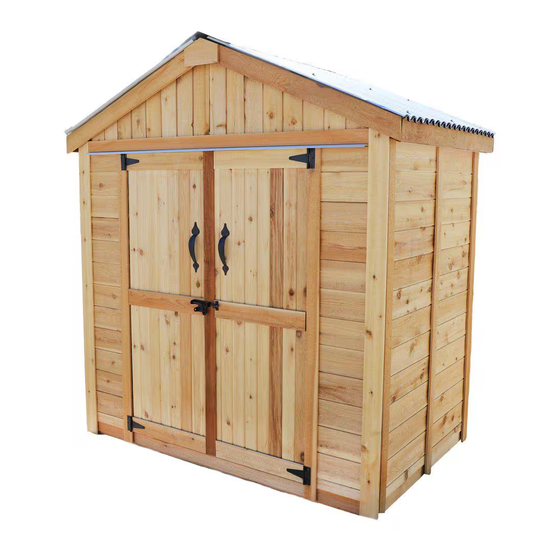
Thank you for purchasing a
6x4 Space Master. Please
take the time to identify all
the parts prior to assembly.
Important Information:
- It is the sole responsibility of the customer to check with your local municipal or county by-laws before
ordering this product to confirm it complies with building codes in your area.
- If the product is elevated, any structural and building code requirements are solely the customer's
responsibility, and should be abided by.
- Snow load ratings vary by geographical location. If heavy or wet snowfall occurs, it is advisable to sweep
snow off roof frequently.
- In areas with high or gusty wind conditions, it is advisable to install the structure securely to the ground.
- Have a regular maintenance plan to ensure screws, doors, windows and parts are tightly affixed.
- All structures purchased from Outdoor Living Today are covered for a period of one year for defects in
manufacturing and workmanship. Costs incurred for customer installations are not included.
- Failure to use supplied parts included in this kit could result in poor product performance and may void your
warranty. Please contact Outdoor Living Today's Customer Toll Free Line if you plan to deviate from our
written instructions.
Customer agrees to hold Outdoor Living Today and any Authorized Dealers free of any liability for improper
installation, maintenance and repair.
In the event of a missing or broken piece, simply call the Outdoor Living Today Customer Support Line
@ 1-888-658-1658 within 30 days of the delivery of your purchase. It is our commitment to you to courier
replacement parts, free of charge, within 10 business days of this notification. Replacement parts will not be
provided free of charge after the 30 day grace period.
Outdoor Living Today
6x4 SPACE
MASTER
WITH DOUBLE DOOR
AND METAL ROOF
ASSEMBLY MANUAL
www.outdoorlivingtoday.com
Page 1
sales@outdoorlivingtoday.com
Advertisement

Related Manuals for OLT SM64-TG-D-METAL


Summary of Contents for OLT SM64-TG-D-METAL
- Page 1 WITH DOUBLE DOOR AND METAL ROOF ASSEMBLY MANUAL Version #1.0 May 31, 2023 Stock Code: SM64-TG-D-METAL Thank you for purchasing a 6x4 Space Master. Please take the time to identify all the parts prior to assembly. Important Information: - It is the sole responsibility of the customer to check with your local municipal or county by-laws before ordering this product to confirm it complies with building codes in your area.
- Page 2 What to do before my Shed arrives? • Become familiar with this assembly manual and determine if you can complete the project yourself or will require a professional contractor. • One helper is recommended to assist in constructing your chalet. It generally takes two people less than a day to assemble a chalet.
- Page 3 Foundation Types for 6x4 Garden Shed 73” 73” 45” 45” Concrete Foundation Floor Frame Completed Foundation Concrete Slab Foundation: - Slab must be at least the same size as assembled floor frame (45” x 73”) or larger. - 6” Deep foundation. - 0.5 Cubic Yards of concrete required.
- Page 4 Thank you for purchasing our 6x4 Space Master with Metal Roof. Please take the time to identify all the parts prior to assembly. Parts List Steps D. - Trim / Misc. Section Cont. Steps 51- 60 Outer Wall Trim and Fascia A.
- Page 5 6x4 SPACE MASTER - DOUBLE DOORS & METAL ROOF Hardware Kit (Provided) 3/4” Black Headed Screw 3” 23 pcs 235 pcs 1 1/2” Finishing 2 1/2” 49 pcs 1 1/2” 5 pcs 40 pcs 2” Black Headed Bolt with Silver Nut and Washer 13 pcs 2”...
- Page 6 Regular Maintenance & Tips to prolong the life of your shed. Before/During Assembly: 1.) Paint each face and edge of your plywood floor with a latex exterior paint. 2.) Caulk wall seams if gaps appear. 3.) Caulk around window framing. 4.) Caulk perimeter between floor plywood and bottom wall plate.
- Page 7 A. Floor Section Exploded view of all parts necessary to complete the Wall Section. Identify all parts prior to starting. Floor Section Floor Joist Parts Locate Floor Joist and position at center of Floor Section Floor Joist and flush with framing as illustrated above. Attach with 2 - 2 1/2” (1 1/2”...
- Page 8 B. Wall Section Exploded view of all parts necessary to complete the Wall Section. Identify all parts prior to starting. Center/Side Front Top Plates (3) Center/Side Rear Front Header Top Plate (3) Interior Door Header Rear Wall Panels (2) Rear/Side Top Wall Plates (6) Side Wall Panels (4)
- Page 9 Rear Wall Panels Side Wall Panels Floor Side Wall Panels Front Narrow Wall Panels With Wall Plates properly attached, orientate completed Walls around the Floor. Be sure to leave room to work. Front Narrow Walls will be required in this section. Wall frame flush with Rear Left Side Wall Before completely...
- Page 10 Rear Left Side Wall Rear Wall With your helper holding the Side Wall Panel, position a Rear Wall Panel in rear corner. Important: Align Wall Framing Flush with Floor Framing. Wall frame flush with outside Floor. Wall siding will overhang Floor. 3”...
- Page 11 Rear Wall Panel 3” Brown Screws 2 1/2” Brown Screw Expert Advice - If you’re placing the shed tight up against a fence or wall, you may consider attaching the Rear Corner and Center Trim on Rear Wall seam first. See Steps 47 - 50.
- Page 12 3” Brown Screws 2 1/2” Brown Screw Wall frame edge flush with outside of Floor on the front. Position second Left Side Wall Panel on Floor. Attach Wall frames together at top, middle and bottom with 3 - 3” Brown Screws. Secure Bottom Wall Plate to floor with 3 - 2 1/2” Brown Screws. Important: Confirm Siding on Side Wall Panels are aligned.
- Page 13 Wall Framings Flush Front Narrow Wall Parts (Steps 11 - 13) Hardware (Steps 11 - 13) Locate Front Narrow Walls and Front Narrow Wall Panels 2 1/2” Brown Screws position Wall framing flush with Side Wall (12 1/2” x 61 3/4”) x 2 x 4 total framing in corner.
- Page 14 2 1/2” Brown screws Narrow Wall Top Plate 2 1/2” Brown Screws 45” Interior Door Header 1 1/4” Brown Screws Front Header Locate Side and Center Top Plates and place on top of the Front Header. With Front Top Plates positioned evenly and flush against Front Header, secure using 6 - 1 1/4”...
- Page 15 1 1/4” Brown Screws Locate and position first Side Wall Top Plate on Side Wall frame so they are flush. Side Wall Top Plates are angle cut down the length. Attach Side Wall Top Plate to Side Wall framing with 4 - 1 1/4”...
- Page 16 Gable framing will overhang Top Plate on the inside approximately 1/8” Locate Front/Rear Gables and position so gable siding sits flush with Wall Siding on the out- side. Gable will fit evenly between Side Wall Top Plates. Temporarily attach Rear Gable to Rear Top Wall Plate with 2 - 2”...
- Page 17 Side Wall Storage Shelf Support Storage Shelf Outdoor Living Today www.outdoorlivingtoday.com sales@outdoorlivingtoday.com Page 17...
- Page 18 C. Rafter and Roof Section Exploded view of all parts necessary to complete the Rafter and Roof Section. Identify all parts prior to starting. Batten Spacers (8) Foam Enclosure (4) Battens (6) Roof Ridge Boards (2) Rafters (6) 41 3/4” Long Rafters 3/4”...
- Page 19 Important: Pilot Hole Ridge Board and Soffit prior to screwing to prevent splitting! Ridge Board Soffit Outdoor Living Today www.outdoorlivingtoday.com sales@outdoorlivingtoday.com Page 19...
- Page 20 Note: Ridge Board must be aligned to bottom of rafter end Rafter should rest Gable Notch on gable framing. Slide Rafter section up on Gable framing until bottom of Ridge Board slips into Gable notch. When Rafter section is correctly positioned, outside rafters will sit equally on Gable framing and soffit will sit approximately 1/4”...
- Page 21 At the peak, align Ridge Boards so they are flush together and secure them with 4 - 1 1/4” Brown Screws. Important: If there is a gap between Ridge Boards, have a helper push the Side Walls closer together from outside. Walls should be 70”...
- Page 22 Important: Pre-drill Batten Spacers with 1/8” bit before fastening. 1/4” from front edge of Rafter Hardware (Step 36 - 40) 1 1/4” Brown Screws x 34 total Outdoor Living Today www.outdoorlivingtoday.com sales@outdoorlivingtoday.com Page 22...
- Page 23 Complete opposite side of roof using remaining Battens and Batten Spacers by following Steps 36 - 39. Outdoor Living Today www.outdoorlivingtoday.com sales@outdoorlivingtoday.com Page 23...
- Page 24 Overhang by 2” Bead of Caulking Parts Staring on one side, locate two Metal Roof Panels and place Metal Roof Panel (43”) x 2 on Battens. Overhang the Metal Roof Panels past the Battens on the sides by approximately 2”. Panels will overlap. Once Metal Roof is spaced correctly from side-to-side and top-to-bottom, lift panels up and run a bead of caulking down the overlapping seams of each panel to seal the joints.
- Page 25 Insert Foam Enclosures Parts Insert Foam Enclosures between Metal Roof Panels and Battens at Foam Enclosures the side. Enclosures may need to be snipped down in length to fit. Enclosures will prevent moisture and unwanted bugs, etc. from entering your shed through here.
- Page 26 D. Miscellaneous Section Exploded view of all parts necessary to complete the Skirting, Trim, Fascia and Miscellaneous Pieces. Identify all parts prior to starting. Metal Ridge Cap Pentagon Detail Plates (2) Front/Rear Fascia Trim (4) Side Facia Trims (2) Front Horizontal Trim Front Wide Corner Trims (2) Filler Trims (8) Left and Right Doors...
- Page 27 Locate Lower Front Skirting (2 Short and 1 Long). Skirting will hide floor framing. Gaps will be covered by Wide Trim pieces later. Attach 2 Lower Short Front Skirting pieces with 2 - 1 1/2” Finishing Nails per piece. Attach Lower Front Long Skirting with 4 - 1 1/2” Finishing Nails. Locate Lower Side and Rear Skirting and attach with 3 - 1 1/2”...
- Page 28 Locate Front Header Filler Strip. Position Front Header Filler Strip onto Front Header. Evenly space from side to side. Secure with 6 - 1 1/2” Finishing Nails into Front Header. Expert Advice: Do a dry run with Front and Rear Corner Trims before attaching.
- Page 29 Hardware 1 1/2” Finishing Nails x 6 total Side Center Trim Rear Side Corner Trim. Side Corner Trim will cap Rear Wide Corner Trim Rear Wide Corner Trim Hardware 1 1/2” Finishing Nails x 6 total Outdoor Living Today www.outdoorlivingtoday.com sales@outdoorlivingtoday.com Page 29...
- Page 30 Tight Underneath Hardware Upper Rear 1 1/2” Finishing Nails Rear Center Trim Horizontal Trim x 6 total Hardware 1 1/4” Screws x 12 total Outdoor Living Today www.outdoorlivingtoday.com sales@outdoorlivingtoday.com Page 30...
- Page 31 Rear Fascia caps Side Fascia. Position Rear Fascia (angle cut on ends) and Side Fascia (square cut ends) in corner. Line Fascia up so Rear Fascia caps Side Fascia. Attach Rear Fascia to Nailing Strip with 6 - 1 1/2” Finishing Nails and Side Fascia to ends of Rafters with 6 - 1 1/2” Finishing Nails. Gap where Fascia boards come together at peak will be covered in Step 52.
- Page 32 Attach Pentagon Detail Plates where Front and Rear Fascia Trims meet at the peak. Secure with 4 - 1 1/2” Finishing Nails per piece. Hardware 1 1/2” Finishing Nails x 8 total Flush with Siding/ Wall Framing Locate 2 Vertical Door Frame Trims. Position on Front Narrow Wall flush with Wall siding/ framing and underneath Front Header Filler Strip.
- Page 33 Door Flange Drill Pilot Holes to prevent splitting. Left Door Right Door Locate Left and Right Doors and Door Flange. Orientate Doors so the outside of each Door is facing up. Locate Black T Hinges. Prior to attaching, position Hinges equally on Door trim as shown above and with a 1/8”...
- Page 34 1/8” 1 - 2” Screw per Hinge Initially. Starting with Right Door first, lift and position Door in opening. Leave a 1/8” gap on right side and 1/8” gap on the bottom. Use a Cedar Shingle Shim to shim the Door at bottom to help position door evenly.
- Page 35 Important: Drill shallow Pilot Holes to prevent splitting. 3/4” Black Screws Drop Latch Receiver 3/4” Black Screws 3/4” Black Screw Attach Black Drop Latch as illustrated above with 6 - 3/4” Black Headed Screws. Note: Black Drop Latch receiver is positioned higher than male. Do a dry run first to position Black Drop Latch correctly.
- Page 36 Wall Framing Parts (Step 73 - 74) Interior Vertical Door Stops (3/4” x 3/4” x 29 7/8”) x 4 Interior Door Stops Outdoor Living Today www.outdoorlivingtoday.com sales@outdoorlivingtoday.com Page 36...
- Page 37 Locate Front Horizontal Trim and Metal Drip Edge. Position Metal Drip Edge behind Door Trim. Evenly space from side to side. While holding down both Metal Drip Edge and Front Horizontal Trim, secure with 6 - 1 1/2” Finishing Nails into Front Header Filler Strip. Parts Front Horizontal Trim (1/2”...
- Page 38 Note: Our Sheds are shipped as an unfinished product. If exposed to the elements, the lumber will weather to a silvery-gray color. If you prefer to keep the lumber looking closer to the original color, we suggest that you treat the wood with a good oil base wood stain.
Need help?
Do you have a question about the SM64-TG-D-METAL and is the answer not in the manual?
Questions and answers