Table of Contents
Advertisement
Quick Links
SERVICE MANUAL
AIR-CONDITIONER
Indoor unit
For R410A:
RAS-M07G3DV-E
RAS-M10G3DV-E
RAS-M13G3DV-E
RAS-M16G3DV-E
RAS-M07G3DV-ND
RAS-M10G3DV-ND
RAS-M13G3DV-ND
RAS-M16G3DV-ND
RAS-M07G3DV-TR
RAS-M10G3DV-TR
RAS-M13G3DV-TR
RAS-M16G3DV-TR
MULTI-SPLIT TYPE
For R32 or R410A:
RAS-M07U2DVG-E
RAS-M10U2DVG-E
RAS-M13U2DVG-E
RAS-M16U2DVG-E
RAS-M22U2DVG-E
RAS-M24U2DVG-E
RAS-M07U2DVG-TR
RAS-M10U2DVG-TR
RAS-M13U2DVG-TR
RAS-M16U2DVG-TR
RAS-M22U2DVG-TR
RAS-M24U2DVG-TR
FILE NO. A10-1413
Revision 5:Jun.2020
Advertisement
Chapters
Table of Contents

Related Manuals for Toshiba RAS-M07G3DV-E


Summary of Contents for Toshiba RAS-M07G3DV-E
- Page 1 FILE NO. A10-1413 Revision 5:Jun.2020 SERVICE MANUAL AIR-CONDITIONER MULTI-SPLIT TYPE Indoor unit For R410A: For R32 or R410A: RAS-M07G3DV-E RAS-M07U2DVG-E RAS-M10G3DV-E RAS-M10U2DVG-E RAS-M13G3DV-E RAS-M13U2DVG-E RAS-M16G3DV-E RAS-M16U2DVG-E RAS-M07G3DV-ND RAS-M22U2DVG-E RAS-M10G3DV-ND RAS-M24U2DVG-E RAS-M13G3DV-ND RAS-M07U2DVG-TR RAS-M16G3DV-ND RAS-M10U2DVG-TR RAS-M07G3DV-TR RAS-M13U2DVG-TR RAS-M10G3DV-TR RAS-M16U2DVG-TR RAS-M13G3DV-TR RAS-M22U2DVG-TR...
-
Page 2: Table Of Contents
CONTENTS 1.SAFETY PRECAUTIONS................2 2. SPECIFICATIONS ..................10 3. REFRIGERANT R410A AND R32..............12 4. CONSTRUCTION VIEWS................24 5. WIRING DIAGRAM..................25 6. SPECIFICATIONS OF ELECTRICAL PARTS ..........26 7. REFRIGERANT CYCLE DIAGRAM............. 27 8. CONTROL BLOCK DIAGRAM ..............28 9. -
Page 3: Safety Precautions
1.SAFETY PRECAUTIONS The important contents concerned to the safety are described on the product itself and on this Service Manual. Please read this Service Manual after understanding the described items thoroughly in the following contents (Indications / Illustrated marks), and keep them. [Explanation of indications] Indication Explanation... - Page 4 Warning Indications on the Air Conditioner Unit [Confirmation of warning label on the main unit] Confirm that labels are indicated on the specified positions If removing the label during parts replace, stick it as the original. Warning indication Description WARNING WARNING ELECTRICAL SHOCK HAZARD ELECTRICAL SHOCK HAZARD...
- Page 5 Precaution for Safety The appliance shall be installed in accordance with national wiring regulations. Capacity shortages of the power circuit or an incomplete installation may cause an electric shock or fire. DANGER Before carrying out the installation, maintenance, repair or removal work, be sure to set the circuit breaker to the OFF position.
- Page 6 WARNIG Before starting to repair the air conditioner, read carefully through the Service Manual, and repair the air conditioner by following its instructions. Only qualified service person (*1) is allowed to repair the air conditioner. Repair of the air conditioner by unqualified person may give rise to a fire, electric shocks, injury, water leaks and/or other problems.
- Page 7 Place a “Work in progress” sign near the circuit breaker while the installation, maintenance, repair or removal work is being carried out. There is a danger of electric shocks if the circuit breaker is set to ON by mistake. When checking the electric parts, removing the cover of the electric parts box of Indoor Unit and/or front panel of Outdoor Unit inevitably to determine the failure, put a sign “Do not enter”...
- Page 8 The refrigerant used by this air conditioner is the R32/R410A.(R32 for some model only). Check the used refrigerant name and use tools and materials of the parts which match with it. For the products which use R32/R410A refrigerant, the refrigerant name is indicated at a position on the outdoor unit where is easy to see.
- Page 9 When the refrigerant gas leaks, find up the leaked position and repair it surely. If the leaked position cannot be found up and the repair work is interrupted, pump-down and tighten the service valve, otherwise the refrigerant gas may leak into the room. When gas touches to fire such as fan heater, stove or cocking stove, it may generate noxious gases, causing a fire though the refrigerant gas itself is innocuous.
- Page 10 Only a qualified installer (*1) or qualified service person (*1) is allowed to install the air conditioner. If the air conditioner is installed by an unqualified individual, a fire, electric shocks, injury, water leakage, noise and/ or vibration may result. Before starting to install the air conditioner, read carefully through the Installation Manual, and follow its instructions to install the air conditioner.
-
Page 11: Specifications
2. SPECIFICATIONS RAS-M07U2DVG-E RAS-M10U2DVG-E RAS-M13U2DVG-E RAS-M16U2DVG-E RAS-M07U2DVG-TR RAS-M10U2DVG-TR RAS-M13U2DVG-TR RAS-M16U2DVG-TR Model Name RAS-M07G3DV-E RAS-M10G3DV-E RAS-M13G3DV-E RAS-M16G3DV-E RAS-M07G3DV-ND RAS-M10G3DV-ND RAS-M13G3DV-ND RAS-M16G3DV-ND RAS-M07G3DV-TR RAS-M10G3DV-TR RAS-M13G3DV-TR RAS-M16G3DV-TR Cooling capacity (Rated) [kW] Cooling Capacity range [kW] Heating Capacity (Rated) [kW] Heating Capacity range [kW]... - Page 12 RAS-M22U2DVG-E RAS-M24U2DVG-E Model Name RAS-M22U2DVG-TR RAS-M24U2DVG-TR Cooling capacity (Rated) [kW] Cooling Capacity range [kW] Heating Capacity (Rated) [kW] Heating Capacity range [kW] Power supply 1Phase, 50Hz, 220-240V / 1Phase, 60Hz, 220V Voltage [V] Running current [A] 0.49 0.47 0.45 0.54 0.52 0.49 Electric characteristics in...
-
Page 13: Refrigerant R410A And R32
3. REFRIGERANT R410A AND R32 Refrigerant R410A 7. Be sure to carry out installation or removal according to the installation manual. This air conditioner adopts the new refrigerant HFC Improper installation may cause refrigeration trouble, (R410A) which does not damage the ozone layer. water leakage, electric shock, fire, etc. - Page 14 2. Safety and Cautions on Installation/Service 10) Carry out the airtight test with nitrogen at a specified pressure. Do not use oxygen or <Safety items> acetylene gas absolutely as it may cause an When gas concentration and ignition energy are explosion.
- Page 15 1) Copper pipe <Piping> The pipe thickness, flare finishing size, flare nut and others differ according to a refrigerant type. When using a long copper pipe for R32, it is recommended to select “Copper or copper-base pipe without seam” and one with bonded oil amount 40mg/10m or less.
- Page 16 4. Tools Tools exclusive for R32/R410A (The following tools for R32/R410A are required.) : R32/R410A tools available : Partly unavailable, : R32/R410A tools unavailable Installation/service tools Applicability to R32/ Applicability to R22 air R410A air conditioner or conditioner or not Tools / Equipment specification 1 Flare tool...
- Page 17 General tools In addition to the above exclusive tools, the following equipments are necessary as the general tools. 1. Pipe cutter 6. Spanner or Monkey wrench 2. Reamer 7. Hole core drill 3. Pipe bender 8. Tape measure 4. Level vial 9.
- Page 18 Labelling • Equipment shall be labelled stating that it has been de-commissioned and emptied of refrigerant. • The label shall be dated and signed. • Ensure that are labels on the equipment stating the equipment contains flammable refrigerant. – 17 –...
- Page 19 Table 3-2-1 Thicknesses of annealed copper pipes Thickness (mm) Nominal diameter Outer diameter (mm) R410A or R32 6.35 0.80 0.80 9.52 0.80 0.80 12.70 0.80 0.80 15.88 1.00 1.00 5. Joints For copper pipes, flare joints or socket joints are used. Prior to use, be sure to remove all contaminants. a) Flare Joints Flare joints used to connect the copper pipes cannot be used for pipings whose outer diameter exceeds 20 mm.
- Page 20 d) Flare Processing Make certain that a clamp bar and copper pipe have been cleaned. ØD By means of the clamp bar, perform the flare processing correctly. Use either a flare tool for R410A/R32 or conventional flare tool. Flare processing dimensions differ according to the type of flare tool.
- Page 21 Table 3-2-6 Flare and flare nut dimensions for R22 Dimension (mm) Nominal Outer diameter Thickness Flare nut width diameter (mm) (mm) (mm) 6.35 9.52 13.0 13.5 9.7 12.70 16.0 16.2 12.9 15.88 19.0 19.7 16.0 19.05 23.3 24.0 19.2 Fig. 3-2-2 Relations between flare nut and flare seal surface 2.
- Page 22 3-3. Recharging of Refrigerant When it is necessary to recharge refrigerant, charge the specified amount of new refrigerant according to the following steps. Recover the refrigerant, and check no refrigerant remains in the equipment. When the compound gauge’s pointer has indicated –0.1 Mpa (–76 cmHg), place the handle Low in the fully closed position, and turn off the vacuum pump’s power switch.
- Page 23 1. Be sure to make setting so that liquid can be charged. 2. When using a cylinder equipped with a siphon, liquid can be charged without turning it upside down. R410A Model It is necessary for charging refrigerant under condition of liquid because R410A is mixed type of refrigerant. Accordingly, when charging refrigerant from the refrigerant cylinder to the equipment, charge it turning the cylinder upside down if cylinder is not equipped with siphon.
- Page 24 • By reducing the brazing filler’s surface tension, the 3-4-3. Brazing brazing filler adheres better to the treated metal. As brazing work requires sophisticated techniques, experiences based upon a theoretical knowledge, it 2. Characteristics required for flux must be performed by a person qualified. •...
-
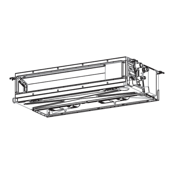
Page 25: Construction Views
4. CONSTRUCTION VIEWS Hanging bolt pitch A Unit external dimension B 25 or less C (Outside) (Only the position of a 1/100 or more check cover.) downward Hanging Flexible drain hose bolt (Accessory) Some models have 300 or less no drain guaid here. Drain-up piping Check cover Refrigerant pipe... -
Page 26: Wiring Diagram
5. WIRING DIAGRAM Color Indication RED:RED BLU:BLUE WHI:WHITE BLK:BLACK CN210 YEL:YELLOW GRN:GREEN (WHI) SW501 BRW:BROWN CN504 T6.3A CN34 (External static (WHI) 250V~ (RED) pressure setup) Main P.C.Board CN104 MCC-1643 t° (YEL) CN22 CN67 CN102 (BLK) t° (RED) TB01 CN71 (CHK) CN101 EARTH t°... -
Page 27: Specifications Of Electrical Parts
6. SPECIFICATIONS OF ELECTRICAL PARTS Model RAS-M***G3DV* ICF-340WD50-1 or ICF-340WD94-3 or ICF-340WD94-3 or RAS-M**G3DV-E/TR WDF-340WD50-1 WDF-340WD94-1 Fan motor RAS-M**G3DV-ND ICF-340WD94-4 Drain pump motor MDP-1401 Float switch FS-1A-31 P.C. board MCC-1643 TA sensor Lead wire length : 328mm Vinyl tube TC sensor Ø6 size lead wire length : 1000mm Vinyl tube (Black) TCJ sensor Ø6 size lead wire length : 1000mm Vinyl tube (Red) -
Page 28: Refrigerant Cycle Diagram
7. REFRIGERANT CYCLE DIAGRAM RAS-M07,10,13G3DV INDOOR UNIT Evaporator Multi-blade fan Connecting pipe Connecting pipe Thickness : 0.8mm Thickness : 0.8mm Sectional shape of heat insulator OUTDOOR UNIT Type 07,10,13 Ø9.52 Ø6.35 Ø12.70 Ø6.35 22,24 Ø12.70 Ø6.35 NOTE : Gas leak check position Refrigerant flow (Cooling) Refrigerant flow (Heating) •... -
Page 29: Control Block Diagram
8. CONTROL BLOCK DIAGRAM Indoor Unit Control Unit M.C.U. Heat Exchanger Sensor (Tcj) Functions Heat Exchanger Sensor (Tc) • Cold draft preventing Function Room Temperature Sensor (Ta) • 3-minute Delay at Restart for Compressor Infrared Rays Signal Receiver • Fan Motor Starting Control and Indication Indoor Fan Motor Control... -
Page 30: Operation Description
9. OPERATION DESCRIPTION 9-1. Outline of Air Conditioner Control................30 9-2. Operation Description....................31 1. Basic operation ......................31 1-1. Operation control ....................31 1-2. When power supply is reset..................32 1-3. Operating mode selection when performing 2-room operation.......32 1-4. Cooling/Heating operation ..................33 1-5. AUTO operation......................34 1-6. -
Page 31: Outline Of Air Conditioner Control
9-1. Outline of Air Conditioner Control This air conditioner is a capacity-variable type air • Detection of inverter input current and current conditioner, which uses DC motor for the indoor fan release operation motor and the outdoor fan motor. And the •... -
Page 32: Operation Description
9-2. Operation Description Item Operation flow and applicable data, etc. Description 1-1. Operation control 1. Basic operation Receiving the user’s operation condition setup, the operation statuses of indoor/outdoor units are controlled. 1) The operation conditions are selected by the remote controller as shown in the below. 2) A signal is sent by ON button of the remote controller. -
Page 33: When Power Supply Is Reset
Item Operation flow and applicable data, etc. Description 1. Basic 1-2.When power supply is reset operation 1) Based on EEPROM data and DIPSW, setting of the indoor fan speed and other setting are loaded. During this loading (approx 30 seconds), operation cannot be accepted. Air speed (rpm) 1-3. -
Page 34: Cooling/Heating Operation
Item Operation flow and applicable data, etc. Description 1. Basic 1-4. Cooling/Heating operation operation The operations are performed in the following parts by controls according to cooling/heating conditions. 1) Receiving the operation ON signal of the remote controller, the cooling or heating operation signal starts being transferred from the indoor controller to the outdoor unit. -
Page 35: Auto Operation
Item Operation flow and applicable data, etc. Description 1. Basic 1-5. AUTO operation operation Remote controller Control outline command • COOL/HEAT operation mode is automatically selected by Ta, Ts Ta: Room temp. and To for operation. Ts: Setup temp. • The operation is performed as To: Outside temp. -
Page 36: Indoor Fan Motor Control
Item Operation flow and applicable data, etc. Description 1) Operation with (HH), (H+), (H), (L+), (L) or [AUTO] mode is carried HH > H+ > H > L+ > L > UL 2. Indoor fan motor out by the command from the remote controller. control 2) When the air speed mode [AUTO] is selected, the air speed varies by the difference between Ta and Ts. - Page 37 Item Operation flow and applicable data, etc. Description 2. Indoor fan Revolution speed of indoor fan (rpm) motor ■ 07, 10 type control External static pressure selection COOL HEAT 10Pa 20Pa 35Pa 45Pa 1020 1120 1200 1260 1020 1120 1200 1260 1020 1120...
- Page 38 Item Operation flow and applicable data, etc. Description ■ [Self-clean ] is displayed. 2. Indoor fan 22 type motor External static pressure selection control COOL HEAT 10Pa 20Pa 35Pa 45Pa 1080 1140 1240 1280 1080 1140 1240 1280 1020 1080 1180 1220 1020...
-
Page 39: Capacity Control
Item Operation flow and applicable data, etc. Description Cool air discharge preventive control In D and E zones, the 2. Indoor fan motor priority is given to air volume 1) In heating operation, the indoor fan is controlled based on the control selection setup of remote detected temperature of Tc sensor or Tcj sensor. -
Page 40: Release Protective Control By Temperature Of Indoor Heat Exchanger
Item Operation flow and applicable data, etc. Description Freeze preventive control (Low temperature release) Tcj: 4. Release protective Indoor heat exchanger 1) The cooling operation (including Dry operation) is performed as control by sensor temperature follows based on the detected temperature of Tc sensor or Tcj temperature sensor. -
Page 41: Drain Pump Control
Item Operation flow and applicable data, etc. Description 1) In cooling operation (including Dry operation), the drain pump is Check code [OB] 5. Drain pump control usually operated. 2) If the float switch works while drain pump drives, the compressor stops, the drain pump continues the operation, and a check code is output. -
Page 42: Intermittent Operation Control For Indoor Fans Of The Indoor Unit At Thermo-Off Side In Heating Operation
7. Intermittent Operation Control for Indoor Fans of the Indoor Unit at Thermo-off Side in Heating Operation While heating operation is executed in two rooms, if room temperature reached the setup temperature in one room and thermo-off occurred, the following operations start. (Refer to the figure below.) 1. -
Page 43: Additional Operation
8. Additional Operation Item Operation flow and applicable data, etc. Description 8-1. QUIET mode When the [QUIET] button is pressed, the fan of the Quiet mode is the system which, control the indoor unit will be restricted the revolving speed at speed revolving speed of indoor fan to work L until the [QUIET] button is pressed once again (cancel constantly at speed L. -
Page 44: Comfort Sleep Mode
Item Operation flow and applicable data, etc. Description Cooling mode The principles of comfort sleep mode are: 8-4. COMFORT SLEEP • The preset temperature will increase as ECO • Quietness for more comfortable. mode operation (Item 8-3.) • Save energy by changing room •... -
Page 45: Frequency Fixed Operation (Test Run)
Item Operation flow and applicable data, etc. Description 11. Frequency <In case of wired remote controller> Command frequency is approximately [S7] fixed Refer to 14-1.Test run setup. operation (Test run) <In case of wireless remote controller> 1) When TEMPORARY button is pushed for 10 seconds or more, “Pi!”... -
Page 46: Self-Cleaning Function
Item Operation flow and applicable data, etc. Description 1. Purpose 12. Self-Cleaning function The Self-Cleaning operation is to minimize the growth of mold, bacteria etc. by running the fan and drying so as to keep the inside of the air conditioner clean. Unit now performing cooling or dry operation Self-Cleaning operation When the cooling or dry operation shuts... -
Page 47: Self-Cleaning Function Release
Item Operation flow and applicable data, etc. Description • Self-Cleaning diagram 12. Self-Cleaning function Operation display FCU fan (Self-Cleaning fan speed) rpm is depend on presetting. PRE, DEF display ON or OFF Compressor depend on presetting per room temperature. ON or OFF CDU fan depend on presetting per room temperature. -
Page 48: Remote-A Or B Selection
Item Operation flow and applicable data, etc. Description Setting the remote controller 1. Purpose 15. Remote-A or B selection To separate using of remote control for each indoor unit This operation is to operate only one in case of 2 air conditioner are installed nearly. indoor unit using one remote controller. -
Page 49: External Static Pressure Settings
Item Operation flow and applicable data, etc. Description There are 2 ways to set external static pressure setting. 17. External static 1) By DIP SW 501-1, -2 [FC [5D]=0000 (factory default) is necessary.] pressure Set the external static pressure setting with the DIP SW501-1, -2 on the indoor unit P.C. board as shown in settings the table below. -
Page 50: Auto Restart Function
9-3. Auto Restart Function This indoor unit is equipped with an automatic restarting function which allows the unit to restart operating with the set operating conditions in the event of a power supply being accidentally shut down. The operation will resume without warning three minutes after power is restored. This function is not set to work when shipped from the factory. -
Page 51: How To Cancel The Auto Restart Function
9-3-2. How to Cancel the Auto Restart Function To cancel auto restart function, proceed as follows : Repeat the setting procedure : the unit receives the signal and beeps three times. The unit will be required to be turned on with the remote controller after the main power supply is turned off. •... -
Page 52: Remote Control
The customized settings control temperature air flow strength, air flow direction and other settings to provide you alternate contact with “ONE-TOUCH” OF THE BUTTON. If you prefer other settings you can select from the many other operation functions of your Toshiba unit Press : Start the operation. - Page 53 4. DRY OPERATION (COOLING ONLY) For dehumidification, a moderate cooling performance is controlled automatically. 1. Press : Select Dry . MODE 2. Press : Set the desired temperature. 5. Hi-POWER OPERATION To automatically control room temperature and airflow for faster cooling or heating operation (except in DRY mode).
- Page 54 9. PRESET OPERATION Set your preferred operation for future use. The setting will be memorized by the unit for future operation (except air flow direction). 1. Select your preferred operation. 2. Press and hold for 3 seconds to memorize the setting. The P mark displays. 3.
-
Page 55: Name And Functions Of Indications On Remote Controller
9-4-3. Name and Functions of Indications on Remote Controller [Display] All indications, except for the clock time indicator, are displayed by pressing the button. Transmission mark TIMER and clock time indicator This transmission mark indicates when the The time setting for timer operation or the clock remote controller transmits signals to the indoor time is indicated. -
Page 56: Owner's Manual And Installation Manual (Excerpt)
The customized settings control temperature, air flow strength and other settings to provide you alternate contact with “ONE-TOUCH” of the button. If you prefer other settings you can select from the many other operating functions of your Toshiba unit. Press : Start the operation. - Page 57 Setting Everyday Timer Air conditioner operating conditions Temp. Outdoor Temperature Room Temperature Press Operation Press : Set the ON timer. Heating Less than 28°C Press button during the Cooling 21°C ~ 32°C Press : Set the OFF timer. ( or ) mark flashing. 17°C ~ 32°C •...
- Page 58 10-2. Accessory parts INSTALLATION MANUAL (EXCERPT) Part name Q’ty Shape Usage Installation Manual This manual (Be sure to hand over to customers) Insulating pipe For insulating pipe connecting section Washer M10 × Ø34 For hanging down the unit Hose band For connecting drain pipe Flexible hose For adjustment of drain pipe centering...
- Page 59 10-3. Selection of installation place Avoid installing in the following places Select a location for the indoor unit where the cool or warm air will circulate evenly. Avoid installation in the following kinds of locations. • Saline area (coastal area) •...
- Page 60 Installation under high-humidity atmosphere In some cases including the rainy season, especially inside of the ceiling may become high-humidity atmosphere (dew-point temperature: 23 °C or higher). 1. Installation to inside of the ceiling with tiles on the roof 2. Installation to inside of the ceiling with slated roof 3.
- Page 61 10-4. Installation CAUTION Strictly comply with the following rules to prevent damage of the indoor units and human injury. • Do not put a heavy article on the indoor unit or let a person get on it. (Even units are packaged) •...
- Page 62 Installation of hanging bolt REQUIREMENT • Consider the piping / wiring after the unit is hung to determine the location of the indoor unit installation and orientation. • Hang the unit in a horizontal position. • After the location of the indoor unit installation has been determined, install When unit is hanged to slant, it may cause overflow of drainage.
- Page 63 Changing from under air intake to back air intake Remove the suction board cover attached to the back, and screw it to the bottom of unit. Suction board Some models have no drain guaid here. Remove the top and bottom fan case screws, and fasten the fan case with the suction board.
- Page 64 How to Install the Signal Receiving Unit To prevent electric shocks, embed the wires in the wall and do not expose them. When installing wires on the wall, be sure to cover them with insulating materials. Note: • To avoid malfunction of the remote controller, do not assemble or run remote control wiring together with the power cables, and do not enclose them in the same metal conduit.
- Page 65 10-5. Drain piping CAUTION Following the Installation Manual, perform the drain piping work so that water is properly drained. Apply a heat insulation so as not to cause a dew condensation. Inappropriate piping work may result in water leakage in the room and wet furniture. •...
- Page 66 Remove the drain pump connector CN504. * For gravitational drainage, remove the white connector (CN504) on the P.C. board in the electrical control box. CN504 White Move the plug to the upper pipe from the lower pipe on the side that will be used. Insert the flexible drain hose into the lower drain pipe and fix it with the hose band.
- Page 67 Heat insulating process • As shown in the figure, cover the flexible hose and hose band with the attached heat insulator up to the bottom of the indoor unit without gap. • Cover the drain pipe seamlessly with a heat insulator locally procured so that it overlaps with the attached heat insulator of the drain connecting section. Wrap the attached heat insulator seamlessly from the surface of the indoor unit.
- Page 68 Fan characteristics 07,10 type Standard Air Volume = 570m Upper limit of external static pressure (45Pa) High (45Pa) Lower limit of external static pressure (45Pa) High (35Pa) Low (45Pa) Low (35Pa) High (20Pa) Low (20Pa) High (10Pa) Low (10Pa) Air Volume (m 13 type Standard Air Volume = 610m Upper limit of external...
- Page 69 22 type Standard Air Volume = 1000m Upper limit of external static pressure (45Pa) High (45Pa) Lower limit of external static pressure (45Pa) High (35Pa) Low (45Pa) Low (35Pa) High (20Pa) Low (20Pa) High (10Pa) Low (10Pa) 1000 1100 1200 Air Volume (m 24 type Standard Air Volume = 1060m...
- Page 70 Connecting method of the duct Connect a duct to the outside of the flange. In addition, the duct must be covered with insulation Duct: Insulation material Flange (locally procured) material so that the flange (locally procured) will not be exposed Aluminum tape (locally procured) Flange Indoor unit...
- Page 71 10-7. Refrigerant piping • Do not scratch the inner surface of the flared part when removing burrs. CAUTION • Flare processing under the condition of scratches on the inner surface of flare processing part will cause refrigerant gas leak. When the refrigerant pipe is long, provide •...
- Page 72 10-8. Electrical connection 1. The supply voltage must be the same as the rated voltage of the air conditioner. 2. Prepare the power source for exclusive use with the air conditioner. NOTE • Wire type : More than H07RN-F or 60245 IEC66 (1.5 mm or more).
- Page 73 10-9. Others External static pressure settings Auto Restart Setting Change the external static pressure setting with the DIP switch on the indoor This product is designed so that, after a power failure, it can restart unit P.C. board. automatically in the same operating mode as before the power failure. Information The product was shipped with Auto Restart function in the off position.
-
Page 74: How To Diagnose The Trouble
11. HOW TO DIAGNOSE THE TROUBLE The pulse motor circuits are mounted to both indoor and outdoor units. Therefore, diagnose troubles according to the trouble diagnosis procedure as described below. (Refer to the check points in servicing written on the wiring diagrams attached to the indoor/outdoor units.) Table 11-1 Troubleshooting Procedure... - Page 75 11-2. Primary Judgment To diagnose the troubles, use the following methods. 1) Judgment by flashing LED of the signal receiving unit 2) Self-diagnosis by service check remote controller 3) Judgment of trouble by every symptom Firstly use the method 1) for diagnosis. Then, use the method 2) or 3) to diagnose the details of troubles. 11-3.
- Page 76 11-4. Self-Diagnosis by Remote Controller (Check Code) 1. If the lamps are indicated as shown B to E in Table 11-3-1, execute the self-diagnosis by the remote controller. 2. When the remote controller is set to the service mode, the indoor controller diagnoses the operation condition and indicates the information of the self-diagnosis on the display of the remote controller with the check codes.
- Page 77 11-4-2. Caution at Servicing 1. After servicing, press the [ ] button to return to the normal mode. 2. After servicing by the check code, turn off breaker of the power supply, and turn on breaker of the power supply again so that memory in the microcomputer returns the initial status.
- Page 78 Block distinction Operation of diagnosis function Judgment and action Check Check Block Cause of operation conditioner Remarks code code status Outdoor Inverter over-current All off Displayed when Even if trying operation again, all P.C. board protective circuit error is detected. operations stop immediately.
- Page 79 Block distinction Operation of diagnosis function Judgment and action Check Check Block Cause of operation conditioner Remarks code code status Others Return serial signal Operation Flashes when 1. Repeat Start and Stop with interval of (including has been sent when continues trouble is approx.
- Page 80 11-5. Judgment of Trouble by Every Symptom 11-5-1. Indoor Unit (Including Remote Controller) (1) Power is not turned on (Does not operate entirely) <Primary check> 1. Is the supply voltage normal? 2. Is the normal voltage provided to the outdoor unit? 3.
- Page 81 (2) Power is not turned on though Indoor P.C. board is replaced <Confirmation procedure> Turn on power supply. Is wired correctly to white and black lead Does operation lamp flash? Correct wiring. wires of terminal board? To item of “Power is not turned on”. –...
- Page 82 (3) Only the indoor motor fan does not operate <Primary check> 1. Is it possible to detect the power supply voltage (AC220–240V) between 1 and 2 on the terminal block? 2. Does the indoor fan motor operate in cooling operation? (In heating operation, the indoor fan motor does not operate for approximately 10 minutes after it is turnedon, to prevent a cold air from blowing in.) Power off.
- Page 83 (4) Troubleshooting for remote control The unit does not beep at all. Press [ OPERATION lamp on indoor button. unit is not indicated. Is transmission mark indicated? Press RESET button on remote control with Is the signal tip of pencil. receiving unit exposed to direct sunlight? Does indoor unit...
- Page 84 11-6. How to Check Simply the Main Parts 11-6-1. How to Check the P.C. Board (Indoor Unit) (1) Operating precautions 1) When removing the P.C. board, be sure to shut off the power supply breaker. 2) When removing the P.C. board, hold the edge of the P.C. board and do not apply force to the parts. 3) When connecting or disconnecting the connectors on the P.C.
- Page 85 (3) Check procedures Table 11-6-1 Procedure Check points Causes Turn off the power supply breaker Check whether or not the fuse (F01) Impulse voltage was applied or the and remove the P.C. board is blown. indoor fan motor short-circuited. assembly from electronic parts base.
- Page 86 11-6-2. P .C . Board Layout Wired remote controller Power supply LED of communication LED microprocessor D504 (Green) D501 (Red) DC fanmotor HA(T10) CN210 (White) CN61 (Yellow), DC12V TA sensor CN104 (Yellow), DC5V Drain pump CN504 (White), DC12V TC sensor Power supply CN101 (Black), DC5V CN67 (Black), AC220V...
- Page 87 11-6-3. Indoor Unit (Other Parts) Part name Checking procedure Room temp. (TA) sensor Disconnect the connector and measure the resistance value with tester. Heat exchanger (TC) sensor (Normal temp.) Temperature 20°C 25°C 30°C 40°C 10°C Sensor TA, TC (kΩ) 20.7 12.6 10.0 Remote controller...
-
Page 88: How To Replace The Main Parts
12. HOW TO REPLACE THE MAIN PARTS WARNING CAUTION Be sure to stop operation of the air conditioner before Be sure to put on gloves during working time; work and then turn off switch of the breaker. otherwise an injury will be caused by a part, etc. Part name Procedure Remarks... - Page 89 Part name Procedure Remarks Electric parts box 1. Detachment Electric parts box cover cover 1) Perform step 1 of “2Terminal cover” as required. (You may be able to perform this procedure without removing the electric parts box cover.) Screws 2) Slightly loosen the screw holding the electric parts box cover in place.
- Page 90 NOISE FILTER 1. Detachment 1) Perform the procedure in 1 of “3 Electric parts box cover.” 2) Remove the binding band from clamp. The claw of 3) The claw of the noise filter (two places) is noise filter removed and remove from the signal receiving unit lead wire.
- Page 91 Part name Procedure Remarks Control P.C. 1. Detachment board 1) Perform the procedure in 1 of “3Electric parts Electric parts box box cover.” 2) Disconnect the connectors from other components from the control P.C. board. NOTE) Unlock the lock of the housing to disconnect the connectors.
- Page 92 Part name Procedure Remarks Fan case 1. Detachment (lower), Fan 1) For the back air intake, perform the procedure case (upper) in 1 of “1Suction panel.” Fan case (upper) 2) Remove the screw on the rear of the fan case Fan case (lower) screw (lower).
- Page 93 Part name Procedure Remarks Fan motor, Multi 1. Detachment blade fan 1) For the back air intake, perform the procedure in 1 of “1Suction panel.” 2) Perform the procedure in steps 1-1), 1-2), 1-3) Clamp of “3Electric parts box cover.” Binding band 3) Disconnect the following connector of the control P.C.
- Page 94 Part name Procedure Remarks Fan motor, Multi NOTE) blade fan Arrange the multi blade fan so that screws position at the right side against the drain pan. NOTE) Fix multi blade fan with torque wrench 4.9 N•m or more. 3) Perform the procedure in steps 2-3) and 2-4) of “8Fan case (lower/upper)”...
- Page 95 Part name Procedure Remarks Under panel, 1. Detachment Drain pan 1) Take off the drain cap and drain the drain water accumulated in the drain pan. Drain cap and drain In case of natural drain model, drain the drain hose Screws water by taking off hose band and drain hose.
- Page 96 Part name Procedure Remarks Drain pump, 1. Detachment Float switch, 1) Perform the procedure in steps 1-1), 1-2), 1-3) Drain hose of “3Electric parts box cover” and 1 of Drain pump Float switch “0Under panel, Drain pan.” Screws * For only drain 2) Disconnect the following connectors and pump connected cables from the control P.C.
- Page 97 Part name Procedure Remarks Heat exchanger 1. Detachment 1) Recover refrigerant, and then remove Sensors refrigerant pipes at indoor unit side. Binding band 2) Perform the procedure in steps 1-1), 1-2), 1-3) of “3Electric parts box cover” and 1 of “0Under panel, Drain pan.”...
-
Page 98: Exploded Views And Parts List
13. EXPLODED VIEWS AND PARTS LIST 13-1. Indoor Unit R410A Model – 97 –... - Page 99 Q’ty/Set Location Part No. Description RAS-M**G3DV-E RAS-M**G3DV-ND RAS-M**G3DV-TR 43H22003 CASE, FAN, UPPER 43H22004 CASE, FAN, UPPER 43H22006 CASE, FAN, LOWER 43H22007 CASE, FAN, LOWER 43H21004 MOTOR, FAN 43H21007 MOTOR, FAN 43H00021 PLATE, INLET 43H00022 PLATE, INLET 43H70001 HOSE, DRAIN 43H44009 REFRIGERATION CYCLE ASSY 43H44010 REFRIGERATION CYCLE ASSY...
- Page 100 R32 or R410A Model – 99 –...
- Page 101 Q’ty/Set Location Part No. Description RAS-M**U2DVG-E, RAS-M**U2DVG-TR 43H22003 CASE, FAN, UPPER 43H22004 CASE, FAN, UPPER 43H22005 CASE, FAN, UPPER 43H22006 CASE, FAN, LOWER 43H22007 CASE, FAN, LOWER 43H22008 CASE, FAN, LOWER 43H21004 MOTOR, FAN 43H21011 MOTOR, FAN 43H00021 PLATE, INLET 43H00022 PLATE, INLET 43H00023...
- Page 102 13-2. E-parts HOLDER SENSOR(TA) TERMINAL 3P PC BOARD ASSY MCC-1643 REACTOR SENSOR TA SENSOR TERMINAL 2P SENSOR Q’ty/Set Location Part No. Description RAS-M**G3DV-E RAS-M**G3DV-ND RAS-M**G3DV-TR 43H58010 REACTOR 43H50010 SENSOR,TC 43H50011 SENSOR,TC 43H50012 SENSOR,TA 43H60013 TERMINAL,3P 43H60014 TERMINAL,2P 43H69018 PC BOARD ASSY, MCC-1643 43H69019 PC BOARD ASSY, MCC-1643 43H69020...
-
Page 103: Appendix
14. APPENDIX Lite-Vision plus Remote Controller (RB-RWS20-E/RB-RWS21-E) setup 1. Test run setup <Procedure> Perform setting while the air conditioner stops. Push the [ MENU] button to display the menu screen. ∨] button at the Push and hold the [ MENU] button and the [ Field setting menu same time to display the “Field setting menu”. - Page 104 Using the Service monitor with the [ MONITOR] button during the test mode Room A 12:00 Test Cool Mode Fan Speed Push the [ MONITOR] button Monitor Function Code Data 0024 Return Refer to “3. Monitor function” for details. 2. Function selection setup Perform the advanced settings for the air conditioner.
- Page 105 Function selection item No. (FC) list Item Contents At shipment from factory 0000: None 0001: 150H Filter sign lighting time 0002: 2500H 0003: 5000H 0000: None 0004: 10000H 0005: Clogging sensor used 0000: Standard Filter stain level 0000: Standard 0001: Heavy stain (Half of standard time) 0000: No shift 0001: +1°C Heating suction temp.
- Page 106 4. Alarm history The error contents in the past can be called. ∧] / [ ∨] button to select “3. Alarm history” on Push the [ Field setting menu the “Field setting menu” screen, then push the “ Set” 1.Test mode F2] button.
- Page 107 Toshiba Carrier Air Conditioning (China) Co., Ltd. Building 1, No.60, 21st Avenue and 2nd Floor, Building 3, No.235, 23st Avenue, Baiyang Street, Hangzhou Economic and Technological Development Area, China Revision record First issue ― ― Sep.2014 Revision 1 Change of knockout hole diameter Page 14 Mar.2015...
Need help?
Do you have a question about the RAS-M07G3DV-E and is the answer not in the manual?
Questions and answers