
Related Manuals for CLIVET MSRN-XSC3 + CEV-XN


Summary of Contents for CLIVET MSRN-XSC3 + CEV-XN
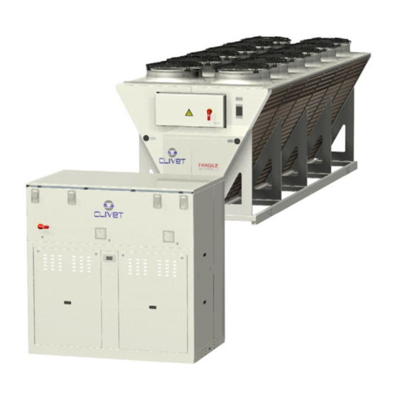
- Page 1 Installation and operating manual MSRN-XSC3 + CEV-XN Air cooled heat pump in two sections M04X00001-01 30-01-2020...
- Page 2 Yours faithfully. CLIVET Spa The data contained in this manual is not binding and may be changed by the manufacturer without prior notice. Reproduction, even is part, is FORBIDDEN © Copyright - CLIVET S.p.A. - Feltre (BL) - Italia...
-
Page 3: Table Of Contents
Index of contents General description Reception Positioning Water connections Refrigeranting connections Electrical connections Start-up Control Maintenance Accessories Decommissioning Residual risks General technical date Dimensional drawings... -
Page 4: General Description
General description 1.1 Manual The manual provides correct unit installation, use and maintenance. Pay particular attention to: Warning, identifies particularly important operations or information. Prohibited operations that must not be carried out, that compromise the operating of the unit or may cause damage to persons or things. •... - Page 5 1.9 User training The installer has to train the user on: • Start-up/shutdown • Set points change • Standby mode • Maintenance • What to do / what not to do in case of breakdown 1.10 Data update Continual product improvements may imply manual data changes. Visit manufacturer web site for updated data.
-
Page 6: Reception
Reception You have to check before accepting the delivery: • That the unit hasn’t been damaged during transport • That the materials delivered correspond with that indicated on the transport document comparing the data with the identification label positioned on the packaging. In case of damage or anomaly: •... - Page 7 2.3 Packaging removing Be careful not to damage the unit. Keep packing material out of children’s reach it may be dangerous. Recycle and dispose of the packaging material in conformity with local regulations. Supports for handling: remove after the handling. Remove the coil protective mesh before the start-up...
-
Page 8: Positioning
Positioning During positioning consider these elements: • Technical spaces requested by the unit • Electrical connections • Water connections • Spaces for air exhaust and intake 3.1 Functional spaces Functional spaces are designed to: • guarantee good unit operation • carry out maintenance operations •... - Page 9 3.4 AxiTop 3.5 Functional spaces 1500 1500 1500 1500 1500 1500 1200 1200 full height wall: standard compliance spaces low height wall: reduced space 3.6 Anti-vibration mount support For details see: 10 Accessories p. 53...
-
Page 10: Water Connections
Water connections 4.1 Water quality Water features • confirming to local regulations • total hardness < 14°fr • within the limits indicated by table The water quality must be checked by qualified personnel. Water with inadequate characteristics can cause: • pressure drop increase •... - Page 11 4.6 Recommended connection The installer must define: • component type • position in system Examples: Standard unit Unit with 2 pumps Unit with VARIFLOW + exchanger drain Anti-ice electric heater Flow Switch water temperature probe System load safety pressure switch differential pressure switch pressure gauge antivibration joints...
- Page 12 – to weld filettare – to thread A + B : fornito da Clivet - Clivet supplied Do not weld the system pipe with the Victaulic connection joint attached. The rubber gasket might be irreparably damaged. 4.8 Water filter...
- Page 13 4.11 Partial energy recovery Option A configuration which enables the production of hot water free-of-charge while operating in the cooling mode, thanks to the partial recovery of condensation heat that would otherwise be rejected to the external heat source. The maximum capacity available from the partial recovery is equal to the 15% of the rejected heating capacity (cooling capacity + compressor power input) The recovery exchanger must be always maintained full of water The lack of water amplifies the noise generated by the operation...
-
Page 14: Refrigeranting Connections
Refrigeranting connections 5.1 Pressure Equipment Directive This unit is a subset: to operate it has to be combined to another unit. It is an installer responsability: • follow the PED Directive and to the national regulations of PED Directive realization •... - Page 15 5.3 General description The sizing of the refrigerating connection lines is of extreme importance for the system operating and reliability. The diameter of the connection between the two units is function of distances, differences in level and curve number; it has so to be calculated by a qualified technician.
- Page 16 Maximum piping length and lift Total equivalent length (m) Max. difference in height (m) The equivalent length is the sum of the effective length of the piping plus a length that is equivalent to the distributed and concentrated pressure drop. To determine the equivalent length refer to tables or data declared by the supplier of the piping.
- Page 17 5.9 Vacuum operations Make sure that all the service outlets are closed with proper caps; if caps are not present a leak of refrigerant can be possible. With the taps of the motor condenser closed, drain the system. Using a gauge group, connect the vacuum pump on both connections of the taps, make sure that the solenoid valve or any intermediate taps are open, proceed with the vacuum.
-
Page 18: Electrical Connections
Electrical connections The characteristics of the electrical lines must be determined by qualified electrica personnel able to design electrical installations; moreover, the lines must be in conformity with regulations in force. The protection devices of the unit power line must be able to stop all short circuit current, the value must be determined in accordance with system features. - Page 19 6.4 Power input Fix the cables: if vacated may be subject to tearing. Respect the minimum distance from the ground to allow the entry of the power line. The cable must not touch the compressor and the refrigerant piping (they reach high temparatures). MSRN-XSC3 CEV-XN 6.5 Connections performer by customer...
- Page 20 MSRN-XSC3...
- Page 21 6.6 Power supply cables section / power bars Size 90.4 100.4 110.4 120.4 140.4 160.4 Min. cable section Cu (mm²) 1x95 1x95 1x150 1x150 1x150 1x240 Max. cable section Cu (mm²) 1x185 1x185 1x240 1x240 1x240 1x240 Min. bar Cu section (mm²) Max.
- Page 22 6.8 Computer connection Service keypad RJ45: standard connection P.C.-not supplied P.C. connection, shift RJ45 from T-HI to T-IP Configure P.C. connect P.C. and main module with LAN cable check in the taskbar that the connection is active open Control Panel and select Network and sharing center select Modify board setting select Local area connection (LAN) select Internet protocol version 4 (TPC) IPV4 and enter Property...
- Page 23 6.9 Remote control Option Distance up to 350 mt User interface Distance up to 700 mt B = B1 KNX bus, max 350 mt twisted pair with shield, ø 0,8 mm EIB/KNX cable marking recommende PSX - Mains power supply unit pwer supply unit N125/11 5WG1 125-1AB11 AC 120...230V, 50...60Hz KNX bus, max 350 mt...
- Page 24 6.10 Modbus - RS485 Option LED BSP communication with AP1 module LED BUS communication with Modbus green communication ok green communication ok yellow software ok but communication with AP1 yellow startup / channel not communicating down flashing: software error communication down fixed: hardware error A.
- Page 25 6.11 LonWorks Option LED BSP communication with AP1 module LED BUS communication with LonWorks green communication ok green ready for communication yellow software ok but communication with AP1 yellow startup down flashing: software error flashing: communicating not possible fixed: hardware error communication down 6.12 BACnet IP Option...
- Page 26 Start-up 7.1 General description The indicated operations should be done by qualified technician with specific training on the product. The electrical, water connections and the other system works are by the installer. Upon request, the service centres performing the start-up. Agree upon in advance the star-up data with the service centre.
- Page 27 7.3 Start-up sequence Unit ON power supply compressor crankcase heaters operating at least since 8 hours off-load voltage measure phase sequence check pump manual start-up and flow check shut-off valve refrigerant circuit open unit ON load voltage measure and absorptions liquid sight glass check (no bubbles) check all fan operating 10.
- Page 28 The above-described operating conditions must be considered outside the operating limits. In the event of compressor breakdown, due to operating in the above-mentioned conditions, the guarantee will not be valid and Clivet spa declines any responsibility.
- Page 29 7.13 Demand limit Menu accessible only after having entered the password. Access reserved only to specifically trained personnel. The parameter modification can cause irreversible damages. It is possible to limit the absorbed electric power with an external signal 0-10 Vcc. The higher the signal is, the lower the number of compressors available to meet the thermal need.
- Page 30 7.14 Climatic TExt Menu accessible only after having entered the password. Access reserved only to specifically trained personnel. The parameter modification can cause irreversible damages. The setpoint defined by the temperature curve is shown at status S0052: ActualUtSetp Only if P0036: EnCompExt ≠ 0 Path: Main Menu / Unit parameters / TExt Correction config Example H e a t i n g...
- Page 31 7.15 Water reset Menu accessible only after having entered the password. Access reserved only to specifically trained personnel. The parameter modification can cause irreversible damages. The water reset correction affects the setpoint defined by the Climate curve TExt (actual setpoint). The setpoint is shown at status S0052: ActualUtSetp Only if P0003: En WaterReset ≠...
- Page 32 7.16 ECOSHARE function for the automatic management of a group of units • Max 7 units • Maximum length of the bus line: 700 m. • Maximum distance between 2 units: 300 m • Type of cable: shielded twisted pair cable Ø 0,8 mm. use an EIB/KNX cable •...
- Page 33 If there are more units connected in a local network set the mode of operation. MODE A Every unit manages its own compressors according to the setpoint. Every unit optimizes its refrigeration circuits. Pumps always active, even with compressor stoped. P0658 = 0 P0657 >...
- Page 34 7.17 Start-up report Identifying the operating objective conditions is useful to control the unit over time. With unit at steady state, i.e. in stable and close-to-work conditions, identify the following data: • total voltages and absorptions with unit at full load •...
- Page 35 Control 8.1 Led INFO Not used ALARM Blink / fixed = alarm present CANCEL not used currently Heat: Heating (not used) 8.2 Display Ref. Variable description Date - Time ActualSetPoint Temperature setting T.InH2OUtilitySide Water inlet temperature utility side T.OutH2OUtilitySide Water outlet temperature utility side ActualState On / off / eco / pmp On Cool: water cooling...
- Page 36 8.4 Change unit state Step Display Action Menu/Variable Keys Notes Press Main menu Select Cmd Local state OFF - ECO - ON - Pump On Confirm Exit * Local state ECO: recurrent pump ON-OFF; compressors keep water system at setpoint ECO Pmp ON: pump ON, compressor OFF 8.5 Change the mode Step Display...
- Page 37 8.7 Scheduler It is possible to set 6 events (Off, Eco, On, Recirculating) for each week day. Step Display Action Menu/Variable Keys Notes Press Main menu Select Scheduler Scheduler Select Select Time Event time Confirm Select Value On/Eco.. Confirm Exit Enable Scheduler Step Display Action...
- Page 38 SOURCE STATA GENERAL STATA Source Pump 1 Command Current Mode Source Pump 2 Command Current Status Source Pump 2 Command Current Setpoint User-side Source Inverter Command Steps Qty Source Inverter Signal Steps On Source Inverter Reset Current Setpoint Recovery 1601 Source Pump 1.1 Hours Alarms 1602...
- Page 39 DIGITAL INPUT ANALOGIC INPUT 2nd Setpoint User-side Demand Limit Recovery System Load User-side Differential Pressure switch User-side System Load Free-cooling Water Temperature Domestic Hot Water Request External Air Temperature Recovery Request Recovery In Temperature User-side Request Recovery Out Temperature F.C. O. YV Cool Cabinet Temperature F.C.
- Page 40 OUTPUT ANALOGICI ANALOGIC OUTPUT User-side YV Bypass Free-cooling Valve Grouped Alarms Recovery Pump Signal Free-cooling Pump 1 1401 Source Fan 1.1 Recovery Pump 1 2401 Source Fan 1.2 Free-cooling Pump 2 Recovery Pump 2 Free-cooling Pump 3 Recovery Pump 3 Anti-freeze Heaters Free-cooling Heaters Cabinet Heating...
- Page 41 8.9 Keyboard settings Step Display Action Menu/Variable Keys Notes Press 3 sec. Press HMI Settings Select Press Press Select Local connections 8.10 Alarms Before resetting an alarm identify and remove its cause. Repeated resets can cause irreversible damage. Example: + eE0001: Phase monitor: Fault = active alarm - EE0003: Pum 1 faulty: Ok = resetted alarm Display of alarm: step 1-3 Reset allarm: step 4-10...
- Page 42 8.11 General list of alarms ELECTRICAL CIRCUIT ALARMS Name Description Category eE0001 Phase monitor Phase monitor fault Central EE0003 Pump 1 faulty User side pump 1 overload protection GP Ut EE0004 Pump 2 faulty User side pump 2 overload protection GP Ut EE0005 Pump 3 faulty...
- Page 43 ELECTRICAL CIRCUIT ALARMS Name Description Category ee0104 TimeOutModPOL965 POL965 module disconnected HW TimeOut ee0105 TimeOutModPOL94U POL94U module disconnected HW TimeOut ee0106 TimeOutModPOL94U_2 POL94U module disconnected HW TimeOut ee0107 TimeOutModPOL985 POL985 module disconnected HW TimeOut ee1001 T.Suction Gas Gas temperature probe 3 fault HW Circuit 1 ee1002 T.Suction Gas...
- Page 44 ELECTRICAL CIRCUIT ALARMS Name Description Category ee1058 Alarm Inverter 2 Inverter 2 in alarm Inverter DFS ee1059 Alarm missing comunication inv2 Inverter 2 Modbus communication error Inverter DFS ee1060 Timeout comunication inv2 Inverter 2 communication timeout Inverter DFS ee1061 Alarm Inverter 3 Inverter 3 in alarm Inverter DFS ee1062...
- Page 45 ELECTRICAL CIRCUIT ALARMS Name Description Category ee2043 Alarm Inverter 3 Inverter 3 in alarm Inverter APY ee2044 Alarm missing comunication inv3 Inverter 3 Modbus communication error Inverter APY ee2045 Timeout comunication inv3 Inverter 3 communication timeout Inverter APY EE2047 Alarm Envelop Comp1 Compressor 1 envelope alarm Circuit 2 EE2048...
- Page 46 EFRIGERANT CIRCUIT ALARMS Name Description Category ff2005 Min overheating EEV1 Min Superheat value (user side) Circuit 2 ff2006 Min overheating EEV2 Min Superheat value (source) Circuit 2 fF2009 Low Pressure Alarm (DI) Low pressure Alarm (DI) Circuit 2 ff2010 Warning LP Cool Low pressure Pre Alarm CoolingMode Circuit 2 ff2011...
- Page 47 Maintenance 9.1 General description Maintenance must be done by authorized centres or by qualified personnel. The maintenance allows to: • maintain the unit efficiency • increase the life span of the equipment • assemble information and data to understand the state of the unit efficiency and avoid possible damages Before checking, please verify the following: •...
- Page 48 9.3 Unit booklet It’s advisable to create a unit booklet to take notes of the unit interventions. In this way it will be easier to adequately note the various interventions and aid any troubleshooting. Report on the booklet: • date •...
- Page 49 9.6 Electric fans Check: • the fans and the relative protection gridsare well fixed • the fan bearings (evident by noise and anomalous vibrations) • the terminal protection covers are closed and the cable holders are properly positioned 9.7 Water side exchanger It is very important for the exchanger to be able to provide the maximum thermal exchange, therefore it is essential for the inner surfaces to be clean of dirt and incrustations.
- Page 50 9.14 Copeland scroll compressor Advanced Scroll Temperature Protection Compressor may stop Pumping With Motor Running Turn Off And Wait Until Cool May need More Than 1 Hour To Reset 9.15 System discharge evacuate the system evacuate the exchanger, use all the present taps use compressed air to blow the exchanger dry completely the exchanger by an hot air jet;...
- Page 51 9.17 Compressor replacement...
- Page 52 9.18 Exchanger replacement...
- Page 53 10 Accessories 10.1 Anti-vibration mount support...
- Page 55 10.2 Hydro Pack Hydropack user side with 2/3 ON/OFF pumps Recovery side hydronic unit with 2/3 inverter pumps Non return valve pressure switch of the charged system Antifreeze heater non utilizzato Couple of manual shut-off valves CSVX drain valve Steel mesh strainer water side IFWX Cutoff valve Differential pressure switch...
- Page 56 11 Decommissioning 11.1 Disconnecting Only authorised personnel must disconnect the unit. Avoid leak or spills into the environment. Before disconnecting the unit, the following must be recovered, if present: • refrigerant gas • anti-freeze solutions in the water circuit Awaiting dismantling and disposal, the unit can also be stored outdoors, if the electrical, cooling and water circuits of the unit have 100% integrity and are isolated, bad weather and rapid change in temperature will not result in any environmental impact.
- Page 57 12 Residual risks General description Electric parts In this section the most common situations are indicated,as these cannot be An incomplete attachment line to the electric network or with incorrectly controlled by the manufacturer and could be a source of risk situations for sized cables and/or unsuitable protective devices can cause electric shocks, people or things.
- Page 58 STANDARD CONFIGURATION Acoustic configuration: compressor soundproofing (SC) General technical data - PERFORMANCE 90.4 100.4 110.4 120.4 140.4 160.4 Internal section size - MSRN-XSC3 105.0 105.0 115.0 130.0 160.0 170.0 External section size - CEV-XN Cooling Cooling capacity [kW] Compressor power input [kW] 76,5 84,8...
- Page 59 DUAL CONFIGURATION Acoustic configuration: compressor soundproofing (SC) General technical data - PERFORMANCE D90.4 D100.4 D110.4 D120.4 D140.4 D160.4 Internal section size - MSRN-XSC3 D105.0 D105.0 D115.0 D130.0 D160.0 D170.0 External section size - CEV-XN Cooling Cooling capacity [kW] Compressor power input [kW] Total power input [kW]...
- Page 60 TRIPLE CONFIGURATION Acoustic configuration: compressor soundproofing (SC) General technical data - PERFORMANCE T110.4 T120.4 T140.4 T160.4 Internal section size - MSRN-XSC3 T115.0 T130.0 T160.0 T170.0 External section size - CEV-XN Cooling Cooling capacity [kW] 1142 1269 Compressor power input [kW] Total power input [kW] Partial recovery heating capacity...
- Page 61 STANDARD CONFIGURATION Acoustic configuration: compressor soundproofing (SC) General technical data - INTERNAL UNIT CONSTRUCTION Internal section size - MSRN-XSC3 90.4 100.4 110.4 120.4 140.4 160.4 Compressor Type of compressors SCROLL Refrigerant R-410A No. of compressors Rated power (C1) [HP] Rated power (C2) [HP] Std Capacity control steps Oil charge (C1)
- Page 62 STANDARD CONFIGURATION EXCELLENCE VERSION Acoustic configuration: compressor soundproofing (SC) General technical data - EXTERNAL UNIT CONSTRUCTION External section size - CEV-XN 90.0 105.0 115.0 120.0 145.0 Fans Type of fans Number of fans Type of motor Standard airflow [l/s] 36779 36143 35703 48075...
- Page 63 Sound levels EXTERNAL SECTION: CEV-XN Compressor soundproofing (SC) Sound power level (dB) Sound Sound Pressure power level level at 10m Octave band (Hz) Size 1000 2000 4000 8000 dB(A) dB(A) 105.0 115.0 130.0 160.0 170.0 Super-silenced (EN) Sound power level (dB) Sound Sound Pressure...
- Page 64 Admissible water flow-rates Minimum (Qmin) and maximum (Qmax) admissible water flow for the unit to operate correctly. EXCELLENCE SC / EN 90.4 100.4 110.4 120.4 140.4 160.4 Qmin [l/s] 10,1 11,5 Qmax [l/s] 18,3 20,0 21,8 25,1 27,5 31,2 Overload and control device calibrations open closed value...
- Page 65 Operating range - Cooling Acoustic configuration: compressor soundproofing (SC) / super-silenced (EN) Ta (°C) = external exchanger inlet air temperature (D.B.) To (°C) = internal exchanger outlet water temperature Standard unit operating range at full load Unit operating range with automatic staging of the compressor capacity Standard unit operating range with air flow automatic modulation.
- Page 66 Dimensional drawings INTERNAL SECTIONS: MSRN-XSC3 Size 90.4 - 160.4 DAA4X0002 _00 DATA/DATE 29/06/2018 1. Compressors 9. Water inlet user side of no pumps unit / Water outlet user side of unit with pumps (optional) 2. Antivibration fixing holes ø 15mm 10.
- Page 67 EXTERNAL SECTION: CEV-XN Size 105.0 - 115.0 - 130.0 DAA5X0001 _00 DATA/DATE 04/06/2018 1. Axitop (removable) 6. Suggested clearance 2. Antivibration fixing holes ø 18mm 7. Circuit 1 liquid line 3. Lifting brackets (removable) 8. Circuit 1 gas line 4. General electrical panel 9.
- Page 68 EXTERNAL SECTION: CEV-XN Size 150.0 - 160.0 - 170.0 - 180.0 DAA5X0002_00 DATA/DATE 04/06/2018 1. Axitop (removable) 6. Suggested clearance 2. Antivibration fixing holes ø 18mm 7. Circuit 1 liquid line 3. Lifting brackets (removable) 8. Circuit 1 gas line 4.
- Page 69 EXTERNAL SECTION: CEV-XN Size 185.0 - 190.0 DAA5X0003 _00 DATA/DATE 04/06/2018 1. Axitop (removable) 6. Suggested clearance 2. Antivibration fixing holes ø 18mm 7. Circuit 1 liquid line 3. Lifting brackets (removable) 8. Circuit 1 gas line 4. General electrical panel 9.
- Page 70 Page intentionally left blank...
- Page 71 Page intentionally left blank...
- Page 72 Tel. +34 91 6658280 - Fax +34 91 6657806 - info@clivet.es CLIVET GmbH Hummelsbütteler Steindamm 84, 22851 Norderstedt - Germany Tel. + 49 (0) 40 32 59 57-0 - Fax + 49 (0) 40 32 59 57-194 - info.de@clivet.com CLIVET RUSSIA Elektrozavodskaya st. 24, office 509 - 107023, Moscow, Russia Tel.
Need help?
Do you have a question about the MSRN-XSC3 + CEV-XN and is the answer not in the manual?
Questions and answers