Table of Contents
Advertisement
Quick Links
Advertisement
Table of Contents

Related Manuals for Mizuho MOT-6302X


Summary of Contents for Mizuho MOT-6302X
- Page 1 Operating Table Operator's Manual MOT-6302X MES-CK18-231-21EN Ver.7 2023-07-14...
-
Page 2: Table Of Contents
3-5. Maintenance Checks & Services ································································································· 37 3-6. Maintenance Matrix ····················································································································· 39 3-7. Service ········································································································································ 41 3-8. Disposal ···················································································································· 41 SECTION IV ELECTROMAGNETIC EMISSIONS ···················································································· 42 Although current at time of publication, MIZUHO's policy of continuous development makes this manual sub- ject to change without notice. -
Page 3: Warranty
Page 2 WARRANTY MIZUHO Corporation will repair defective parts of this product without charge for one year from the date of delivery/installment except for cases of damage caused by a third party's repair, act of nature, improper use or damage on purpose. All other warranty terms and conditions are subject to... -
Page 4: Equipment Labels
Page 3 EQUIPMENT LABELS C642002 C656339 YYYY-MM-DD Made in *** C653529 C656328(EU) C656329(AUST/NZ) 6 0 0 J U 5 7 C656333(EU) C656334(AUST/NZ) 6 3 2 D U 0 3... -
Page 5: Symbol Mark For Labeling
Page 4 Symbol mark for labeling Used On Used In Symbol Description Product Manual Indicates important facts or helpful hints NOTE General warning sign (WARNING, CAUTION) ISO 7010-W001 General prohibition sign ISO 7010-P001 Blue General mandatory action sign ISO 7010-M001 Blue Refer to instruction manual ISO 7010-M002... - Page 6 Page 5 Symbol mark for labeling Used On Used In Symbol Description Product Manual Emergency stop IEC 60417-5638 Type B applied part IEC 60417-5840 Defibrillation-proof Type B applied part IEC 60417-5841 IPX4 Enclosure class (Splash-proof) IEC 60529 Indicates waste disposal information WEEE Earth (ground) IEC 60417-5017...
- Page 7 Page 6 TABLE SPECIFICATIONS 320 mm 463 mm 455 mm 585 mm TOP VIEW 326 mm 1980 mm 60° 500 mm 100 mm 52 mm 90° 1012 mm 634 mm 483 mm 923 mm FRONT VIEW SIDE VIEW Maximum Lifting Capacity: 450kg Unit Weight: 320kg Maximum Articulating Capacity: 270kg Maximum Patient Weight: 450kg...
- Page 8 Page 7 TABLE SPECIFICATIONS Environmental Condition Condition of Use Condition of Transport and Storage Ambient Temperature 10 - 40°C -10 - 50°C 10 - 85% Relative Humidity 30 - 75% (No Condensation) Atmospheric Pressure 700 - 1060 hPa 700 - 1060 hPa Operating altitude 2000 m max above sea level...
-
Page 9: Inspections Performed Prior To Placing Unit Into Use
Page 8 After long period of storage - these items should be checked: INSPECTIONS PERFORMED PRIOR TO PLACING UNIT INTO USE Description: Completed 1. Mains Power Function - ON/OFF Operation and LED battery function 2. Battery Power Function / Mode 3. -
Page 10: Special User Attention
The maximum lifting capacity of the MOT-6302X table is 450kg and the maximum articulation weight capacity is 270kg. When lifting or articu- lating large patients, pay close attention to the... - Page 11 Page 10 SPECIAL USER ATTENTION WARNING Possible Pinch / Crush Points HEAD & BACK SECTION CAN COLLIDE WITH BASE LEG SECTION AND ELEVATION COLUMN CAN COLLIDE LEG SECTION AND FLOOR CAN COLLIDE...
- Page 12 Contact an authorized MIZUHO repre- sentative for disposal instructions for NOTE the MIZUHO Surgical Table that are in accordance with current environmental Activating any function button will acti- regulations for medical products. vate the brake system. Using the...
- Page 13 BATT ON/OFF switch. supply main with Protective earth. Power Cord has to be used the one NOTE which has a logotype of MIZUHO. The table can be operated on AC power while the battery is being recharged. WARNING Please don't position the surgical table...
- Page 14 Page 13 SPECIAL USER ATTENTION NOTE WARNING With an evenly distributed patient Please confirm that the operating table weight load, all table positioning func- is fixed stably after applying the brakes. tions will operate smoothly and quietly with a patient weight of up to 270kg. WARNING DO NOT unlock brakes when a patient WARNING...
- Page 15 Page 14 SPECIAL USER ATTENTION NOTE WARNING emergency back-up control Make sure the TOP ROTATION LOCK switches will function when the table is HANDLE is tightened and the brakes operating on AC power, battery power, are set before transferring the patient. or turned off.
- Page 16 Usable mattresses are as following. genuine MIZUHO accessories. 50005M3 Accessories and products not furnished 672C6M1 by MIZUHO have not been tested for 672C8M1 proper performance and safety. Such applications or use are at the discretion Mattress's shape is suitable for each of the user to ensure patient and staff table board.
- Page 17 The operating table should only be ser- diately and labeled inoperable. Refer all viced or maintained by a factory trained service to a MIZUHO authorized ser- personnel. vice representative. NOTE The elevation cylinder should be com-...
-
Page 18: Section I Introduction
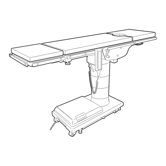
The battery charging indicator and an area for an knowledge of this product. optional foot control connector are also located on the electrical panel. MIZUHO’s MOT-6302X Surgical Table is an elec- trohydraulically operated, general purpose surgical table. See figure 1-1. The electro-hydraulic positioning functions operated... -
Page 19: Pendant Control Unit
Protective Earth Ground is compro- operation will be stopped. The thermal mised equipment must be operated on protector will reset in approximately 30 battery mode. minutes. Use only MIZUHO Replacement Parts NOTE for power cord and pendant control. operating table built-in Refer to Replacement Parts Section. -
Page 20: Floor Lock/Brake System
Page 19 SECTION I INTRODUCTION 1-4. Floor Lock/Brake System The floor lock/brake system consists of four self-leveling, hydraulic brake cylinders which raise and support the table base off from the casters. Press the TABLE UP button on the pendant control to set the table’s brakes. -
Page 21: Section Ii Operation
To avoid the risk of electric shock, this culty to disconnect the Equipment by equipment must only be connected to a plug or appliance outlet. supply main with Protective earth. Power Cord has to be used the one which has a logotype of MIZUHO. -
Page 22: Battery Operation
Page 21 SECTION II OPERATION c. The table is now ready for BATTERY operation. 2-3. Battery Operation d. To extend the battery charge life, turn the a. Make sure the Main Power Switch indicator light, BATTERY power OFF with the pendant control on the electrical panel, is OFF. -
Page 23: Charging The Battery
Page 22 SECTION II OPERATION 2-5. Charging the Battery Batteries should be charged: When the table is placed into initial service As indicated by Battery Charge Indicator Every week under normal service conditions POWER CORD POWER SWITCH BATTERY INDICATOR FOOT SWITCH Prior to all surgical procedures a. -
Page 24: Positioning Functions
Page 23 SECTION II OPERATION OPERATOR’S 180° WARNING POSITION If the table is stored for a period greater than 6 months, the batteries should be removed and stored in a dry, clean PATIENT’S HEAD condition at a storage temperature of HEAD SECTION 68°F (20°C). - Page 25 Page 24 SECTION II OPERATION Press the BRAKE UNLOCK button on the pendant WARNING control to release the four self-leveling brake feet in order to move the table. See figure 2-7. The brake Prior to unlocking brakes, check for ob- structions on the floor that might pre- delay circuit automatically retracts the brake system.
- Page 26 Page 25 SECTION II OPERATION d. Back Section To raise the back section, press REVERSE TRENDELENBURG the BACK UP button (figure 2-10). The back section TRENDELENBURG will raise up to 90° above horizontal. To lower the back section, press the BACK DOWN button. The back section will go down to 40°...
- Page 27 Page 26 SECTION II OPERATION f. Leg Section To lower the leg section, press the h. Return To Level To return the table top to a LEG DOWN button (figure 2-12). The leg section will level position, press the LEVEL button (figure 2-14). go down to 100°...
-
Page 28: Emergency Switch
Page 27 SECTION II OPERATION b. In the event of either a power failure or a problem 2-7. Emergency Switch with the hand-held pendant control, the table can be operated using the emergency back-up switches. Emergency switch is above the top rotation handle. Simply push the desired emergency switch in the appropriate direction to operate the table functions. -
Page 29: Emergency Brake Release
Page 28 SECTION II OPERATION 2-9. Emergency Brake Release SERVICE ACCESS COVER In case of a power failure or an electrical problem within the table, the emergency brake release sys- tem can be used to move the table. The control knob for this function is located on the side of the table base and is identified by an EMERGENCY BRAKE BRAKE (4) -
Page 30: Leg Section Removal
LEG-UP button until the leg section attachment pins completely stop before reinstalling the leg section to The MOT-6302X Table has the capability of attach- the table. Pull out on the leg section after installation ing the head section to the leg section for use as a to make sure the release levers are completely foot extension ONLY. -
Page 31: Kidney Lift
Page 30 SECTION II OPERATION 2-13. Kidney Lift WARNING Make sure the TOP ROTATION LOCK a. The built-in kidney lift is operated by a manual HANDLE is tightened and the brakes hand crank system and allows 100mm of lift. See are set before transferring the patient. -
Page 32: Positioning
SECTION II OPERATION 2-14. Positioning The use of certain optional accessories available MATTRESS from MIZUHO further extend the positioning capa- bilities of the MOT-6302X Tables. Refer to the op- tional accessories manual or contact your MIZUHO representative for further details. TABLE WARNING Certain accessories may limit weight capacities. - Page 33 Usable mattresses are as following. 50005M3 672C6M1 672C8M1 Mattress's shape is suitable for each table board. Tag which indicates that a mattress is an applied part and is made by MIZUHO is attached on a mattress. 50005M3 672C6M1 672C8M1 Figure 2-28. Tag of Mattress...
-
Page 34: Section Iii Maintenance
Check that active ingredients of the try into electrical connectors. product are compatible with the materials of the MIZUHO Table. a. Cleaning Apply cleaning fluid liberally to top and sides of each pad and wipe with a clean lint-free cloth. -
Page 35: Routine Inspections
Page 34 SECTION III MAINTENANCE When the cleaning procedure is complete, replace Usable antiseptic solutions which we have already all pads and accessories as applicable. confirmed are as the following lists. Use the antiseptic solutions listed as follows. Remove disconnected pendant control from table side rail and apply cleaning solution to the pendant Medicine Name control and cord. -
Page 36: Preventive Maintenance
3-3. Preventive Maintenance The following preventive maintenance checks and services are recommended to ensure the servicea- bility and proper operation of your MIZUHO Surgical Table. Maintenance must be performed by a MIZUHO authorized service representative using MIZUHO authorized replacement parts and service techniques. -
Page 37: Operator Troubleshooting
2red Replacement and reconnect of battery and fuse and reset of breaker have to be performed by trained service staff of MIZUHO. If corrective actions for the following symptoms are necessary, be sure to contact an agency of MIZUHO. -
Page 38: Maintenance Checks & Services
Refer all Place a small amount of White Lithium Grease on service to a MIZUHO authorized ser- the Head Section Release Bar Plunger and the vice representative. Head Section Trunnion Gears. - Page 39 Leg Section to level. This micro-switch ad- justment, if needed, can only be performed by a MIZUHO authorized service representative. Ensure the Table Top Rotation Locking Handle is present and secures the Table Top from excessive movement when tightened.
-
Page 40: Maintenance Matrix
For optimal usage, pinched, or otherwise damaged. safety and longevity of the product, have it serviced only by a MIZUHO authorized service representa- Test each Hand Control Pendant Articulation Button tive using MIZUHO authorized replacement parts for full range of travel. - Page 41 Page 40 SECTION III MAINTENANCE SURGICAL TABLE MAINTENANCE MATRIX Component 1 Year 2 Years 5 Years 7 Years Lateral Tilt Housing Bolts Trendelenburg End Cap Bolts Side Rails & Gravity Stops Velcro Hydraulic Oil Level A.C. Power Cord Self-Leveling Brake Pad Casters Lubricate Elevation Column Tighten X-Ray Top Standoffs &...
-
Page 42: Service
3-30-13 Hongo, Bunkyo-ku techniques. Tokyo 113-0033, Japan https://www.mizuho.co.jp Preventive Maintenance contracts are available through your local MIZUHO representative. European authorized representative: EMERGO EUROPE To obtain MIZUHO authorized service or preventive Westervoortsedijk 60 maintenance contracts, contact your nearest 6827 AT Arnhem,... -
Page 43: Section Iv Electromagnetic Emissions
Normal operation may not be possible due to electromagnetic interference. Guidelines and manufacturer declaration – electromagnetic emissions The MOT-6302X is intended for use in the electromagnetic environment specified below. The customer or user of the MOT-6302X must ensure that it is operated in suchlike environments. Electromagnetic Compliance Electromagnetic environment –... - Page 44 SECTION IV ELECTROMAGNETIC EMISSIONS Guidelines and manufacturer declaration – electromagnetic interference immunity The MOT-6302X is intended for use in the electromagnetic environment specified below. The customer or user of the MOT-6302X must ensure that it is operated in suchlike environments. Interference Electromagnetic...
- Page 45 RF transmitter, it is desirable to consider an electromagnetic field survey. If the measured field strength exceeds the compliance level as specified above at the location where the MOT-6302X is used, the MOT-6302X should be observed to verify correct functionality.If abnormal performance is observed,...
- Page 46 Page 45...
- Page 47 Sales Agent EMERGO EUROPE MIZUHO Corporation Westervoortsedijk 60 6827 AT Arnhem, The Netherlands 3-30-13 Hongo, Bunkyo-ku Tokyo 113-0033, Japan https://www.mizuho.co.jp...
Need help?
Do you have a question about the MOT-6302X and is the answer not in the manual?
Questions and answers