Mitsubishi Electric SLZ Series Technical & Service Manual
Split-system heat pump
Hide thumbs
Also See for SLZ Series:
- Technical & service manual (78 pages) ,
- Technical & service manual (32 pages) ,
- Technical & service manual (60 pages)
Advertisement
Table of Contents
- 1 Table of Contents
- 2 Reference Manual
- 3 Safety Precaution
- 4 Parts Names and Functions
- 5 Specifications
- 6 Outlines and Dimensions
- 7 Wiring Diagram
- 8 Refrigerant System Diagram
- 9 Troubleshooting
- 10 Special Function
- 11 Way Airflow System
- 12 Disassembly Procedure
- 13 Remote Controller
- Download this manual
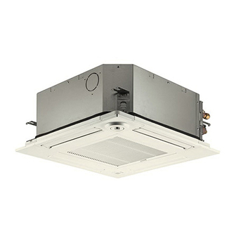
SPLIT-SYSTEM HEAT PUMP
TECHNICAL & SERVICE MANUAL
Indoor unit
[Model Name]
SLZ-KF09NA1
SLZ-KF12NA1
SLZ-KF15NA1
SLZ-KF18NA1
Model name
indication
INDOOR UNIT
WIRELESS REMOTE
CONTROLLER
(Option)
[Service Ref.]
SLZ-KF09NA1
SLZ-KF12NA1
SLZ-KF15NA1
SLZ-KF18NA1
ON
RETURN SELECT
MENU
HOLD
OFF
WIRED REMOTE CONTROLLER
(Option)
CONTENTS
1. REFERENCE MANUAL ...................... 2
2. SAFETY PRECAUTION ...................... 2
3. PARTS NAMES AND FUNCTIONS ..... 6
4. SPECIFICATIONS ............................... 7
5. OUTLINES AND DIMENSIONS ........... 9
6. WIRING DIAGRAM ............................ 10
7. REFRIGERANT SYSTEM DIAGRAM ..... 11
8. TROUBLESHOOTING ....................... 12
9. SPECIAL FUNCTION ........................ 26
10. 4-WAY AIRFLOW SYSTEM ............... 27
11. DISASSEMBLY PROCEDURE .......... 29
12. REMOTE CONTROLLER .................. 33
PARTS CATALOG (TCB118)
April 2023
No. TCH118
Advertisement
Table of Contents

Related Manuals for Mitsubishi Electric SLZ Series


Summary of Contents for Mitsubishi Electric SLZ Series
-
Page 1: Table Of Contents
SPLIT-SYSTEM HEAT PUMP April 2023 No. TCH118 TECHNICAL & SERVICE MANUAL Indoor unit [Model Name] [Service Ref.] SLZ-KF09NA1 SLZ-KF09NA1 SLZ-KF12NA1 SLZ-KF12NA1 SLZ-KF15NA1 SLZ-KF15NA1 SLZ-KF18NA1 SLZ-KF18NA1 CONTENTS 1. REFERENCE MANUAL ...... 2 2. SAFETY PRECAUTION ...... 2 3. PARTS NAMES AND FUNCTIONS ..6 4. -
Page 2: Reference Manual
REFERENCE MANUAL OUTDOOR UNIT’S SERVICE MANUAL Model Name Service Ref. Service Manual No. / Parts catalog No. MXZ-2C20NA2 MXZ-2C20NA2 (-U1) MXZ-2C20NA2 MXZ-2C20NA2 (-U4) MXZ-3C24/30NA2 MXZ-3C24/30NA2 (-U1) MXZ-4C36NA2 MXZ-4C36NA2 (-U1) MXZ-5C42NA2 MXZ-5C42NA2 (-U1) MXZ-2C20NAHZ2 MXZ-2C20NAHZ2 (-U1) MXZ-3C24/30NAHZ2 MXZ-3C24/30NAHZ2 (-U1) MXZ-2C20/24/30NA3 MXZ-2C20/24/30NA3 (-U1) MXZ-4C36NA3 MXZ-4C36NA3 (-U1) OBH702 / OBB702... - Page 3 Precautions during the repair service. Preparation before the repair service. • Prepare the proper tools. • Do not perform the work involving the electric parts • Prepare the proper protectors. with wet hands. • Provide adequate ventilation. • Do not pour water into the electric parts. •...
- Page 4 [1] Warning for service (1) Do not alter the unit. (2) For installation and relocation work, follow the instructions in the Installation Manual and use tools and pipe components specifically made for use with refrigerant specified in the outdoor unit installation manual. (3) Ask a dealer or an authorized technician to install, relocate and repair the unit.
- Page 5 Unit Electronic weighing scale [4] Service tools Use the below service tools as exclusive tools for R410A refrigerant. Tool name Specifications Gauge manifold · Use the existing fitting specifications . (UNF1/2) · Use high-tension side pressure of 5.3MPa·G [768.7 PSIG] or over. Charge hose ·...
-
Page 6: Parts Names And Functions
PARTS NAMES AND FUNCTIONS Filter Removes dust and pollutants Horizontal Air Outlet from drawn in air. Sets horizontal airflow automatically during cooling or dehumidifying. Grille Auto Air Swing Vane Disperses airflow up and down and adjusts the angle of airflow direction. Air Intake Draws in air from room. -
Page 7: Specifications
SPECIFICATIONS Indoor unit service ref. SLZ-KF09NA1 SLZ-KF12NA1 SLZ-KF15NA1 SLZ-KF18NA1 Mode Cooling Heating Cooling Heating Cooling Heating Cooling Heating Power supply (phase, cycle, voltage) Single phase 208/230 V, 60Hz Input [kW] 0.02 0.02 0.02 0.02 0.03 0.03 0.04 0.04 Current* 0.20 0.15 0.24 0.19... - Page 8 NOISE CRITERION CURVES <60Hz> <60Hz> SLZ-KF09NA1 SLZ-KF12NA1 NOTCH SPL(dB) LINE NOTCH SPL(dB) LINE High High Medium Medium NC-70 NC-70 NC-60 NC-60 NC-50 NC-50 NC-40 NC-40 NC-30 NC-30 APPROXIMATE APPROXIMATE THRESHOLD OF THRESHOLD OF HEARING FOR HEARING FOR NC-20 NC-20 CONTINUOUS CONTINUOUS NOISE NOISE...
-
Page 9: Outlines And Dimensions
OUTLINES AND DIMENSIONS SLZ-KF09NA1 SLZ-KF12NA1 SLZ-KF15NA1 SLZ-KF18NA1 Unit: inch (mm) TCH118... -
Page 10: Wiring Diagram
WIRING DIAGRAM SLZ-KF09NA1 SLZ-KF12NA1 SLZ-KF15NA1 SLZ-KF18NA1 TCH118... -
Page 11: Refrigerant System Diagram
REFRIGERANT SYSTEM DIAGRAM SLZ-KF09NA1 SLZ-KF12NA1 SLZ-KF15NA1 SLZ-KF18NA1 Strainer Heat exchanger Refrigerant GAS pipe connection (Flare) Condenser/evaporator temperature thermistor (TH5) Refrigerant flow in cooling Refrigerant flow in heating Refrigerant LIQUID pipe connection (Flare) Pipe temperature thermistor/liquid Room temperature (TH2) thermistor (TH1) Strainer Distributor with strainer Unit: inch(mm) SLZ-KF09/12NA1 SLZ-KF15/18NA1... -
Page 12: Troubleshooting
TROUBLESHOOTING 8-1. TROUBLESHOOTING <Check code displayed by self-diagnosis and actions to be taken for service (summary)> Present and past check codes are logged, and they can be displayed on the wired remote controller or controller board of out- door unit. Actions to be taken for service, which depends on whether or not the trouble is reoccurring in the field, are summa- rized in the table below. - Page 13 [Output pattern A] Errors detected by indoor unit Wired remote Wireless remote controller controller Symptom Remark Beeper sounds/OPERATION INDICATOR lamp blinks Check code (Number of times) Intake sensor error P2, P9 Pipe (liquid or 2-phase pipe) sensor error E6, E7 Indoor/outdoor unit communication error Float switch connector open Drain pump error...
- Page 14 ● If the unit cannot be operated properly after test run, refer to the following table to find the cause. Symptom Cause Wired remote controller LED 1, 2 (PCB in outdoor unit) Please Wait For about 3 After LED 1, 2 are lit, LED 2 is turned •...
- Page 15 Note: Errors to be detected in outdoor unit, such as codes starting with F, U or E (excluding E0 to E7), are not covered in this document. Please refer to the outdoor unit's service manual 8-3. SELF-DIAGNOSIS ACTION TABLE for the details. Check code Abnormal point and detection method Countermeasure...
- Page 16 *1: only P-series outdoor unit Check code Abnormal point and detection method Countermeasure Cause Drain pump lock protection operation 12 Check if drain pump works. 1 Malfunction of drain pump 1 Suspected abnormality, if drain pump 2 Clogged drain pump Check if connector (CNP) is connected.
- Page 17 *1: only P-series outdoor unit Check code Abnormal point and detection method Countermeasure Cause Pipe temperature thermistor/Condenser / Evaporator (TH5) 1 Defective thermistor 1– Check resistance value of thermistor. 1 The unit is in 3-minute resume protec- characteristics For characteristics, refer to (P1). tion mode if short/open of thermistor is detected.
- Page 18 Abnormal point and detection method Countermeasure Check code Cause Remote controller transmission error(E3)/ signal receiving error(E5) 1 2 remote controllers are set as 1 Set a remote controller to main, and the other 1 Abnormal if remote controller could not “main.”...
- Page 19 Check code Abnormal point and detection method Countermeasure Cause Forced compressor stop (due to water leakage abnormality) 1 The unit has a water leakage abnormality 1 Drain pump trouble 1 Check the drain pump. when the following conditions, a) and b), 2 Drain defective 2 Check whether water can be drained.
- Page 20 8-4. TROUBLESHOOTING OF PROBLEMS Note: Refer to the manual of outdoor unit for the detail of remote controller. *1: only P-series outdoor unit Phenomena Cause Countermeasure (1) LED2 on indoor controller board • When LED1 on indoor controller board is also off. is off.
- Page 21 Note: Refer to the outdoor unit's service manual for the detail of remote controller. Phenomena Cause Countermeasure (3)Upward/downward vane The vane is not downward during defrosting and heat Normal operation (The vane is set to hori- performance failure preparation and when the thermostat is OFF in HEAT zontal regardless of remote control.) mode.
- Page 22 8-5. TEST POINT DIAGRAM 8-5-1. Indoor controller board SLZ-KF09NA1 SLZ-KF12NA1 SLZ-KF15NA1 SLZ-KF18NA1 LED2 CN90 CN4Z CN22 Power supply Connect to the wireless i-see Sensor (Sensor) (Wired remote controller) remote controller board (CNB) Connect to the terminal black (TB5) (Remote controller transmission line) Vane motor (MV) 12 V pulse output Model selection CN5Y...
- Page 23 8-6. FUNCTION OF DIP SWITCH Each function is controlled by the DIP switch on the indoor controller board. Model setting and capacity setting are preset in the nonvolatile memory of the indoor controller board. ■ The black square ( ) indicates a switch position. Setting by the DIP switch and jumper wire Switch Functions...
- Page 24 8-7. TROUBLESHOOTING OF MAIN PARTS SLZ-KF09NA1 SLZ-KF12NA1 SLZ-KF15NA1 SLZ-KF18NA1 Parts name Check method and criterion Room temperature Measure the resistance with a tester. thermistor (TH1) (Parts temperature 50 to 86°F) Pipe temperature Normal thermistor/liquid (TH2) 4.3 to 9.6 k" Condenser/evaporator temperature thermistor (TH5) (Refer to "8-7-1.
- Page 25 8-7-1. Thermistor Characteristic Graph < Thermistor for lower temperature > <Thermistor characteristic graph> Room temperature thermistor (TH1) Thermistor for Pipe temperature thermistor/liquid (TH2) lower temperature Condenser/evaporator temperature thermistor (TH5) Thermistor R =15 k" ± 3% Fixed number of B=3480 ± 2% t(˚C)Rt=15exp { 3480( 273+t T(˚F)Rt=15exp { 3480(...
-
Page 26: Special Function
SPECIAL FUNCTION BACK-UP HEATING FUNCTION 9-1. Operation The back-up heater turns ON when both of the following conditions have been satisfied: A) When the room temperature has not risen after the heater ON delay time has passed. Note: The heater ON delay time starts when the condition of “set temperature − room temperature > 1°F [0.5°C]” has been satisfied. B) Set temperature −... -
Page 27: Way Airflow System
4-WAY AIRFLOW SYSTEM 10-1. FRESH AIR INTAKE (LOCATION FOR INSTALLATION) At the time of installation, use the duct holes (cut out) located at the positions shown in following diagram, as and when required. Fresh air intake Detail drawing of fresh air intake (Unit: inch) 5-17/32 Burring hole... - Page 28 10-4. FIXING HORIZONTAL VANE Horizontal vane of each air outlet can be fixed according to the environment where it is installed. Setting procedure 1) Turn off the main power supply (Turn off the breaker). 2) Remove the vane motor connector in the direction of the arrow shown below with pressing the unlocking button as in the figure below.
-
Page 29: Disassembly Procedure
DISASSEMBLY PROCEDURE SLZ-KF09NA1 SLZ-KF12NA1 SLZ-KF15NA1 SLZ-KF18NA1 Be careful when removing heavy parts. OPERATING PROCEDURE PHOTOS/FIGURES 1. Removing the air intake grille and air filter Figure 1 Grille hook (1) Slide the knob of air intake grille to the direction of the arrow 1 to open the air intake grille. Air intake grille Air fi lter (2) Remove the grille hook from the panel to prevent the... - Page 30 OPERATING PROCEDURE PHOTOS/FIGURES 3. Removing the electrical parts Photo 4 (1) Loosen the 2 screws on the control box cover. Control box cover (2) Slide the control box cover as indicated by the arrow to remove. <Electrical parts in the control box> •...
- Page 31 OPERATING PROCEDURE PHOTOS/FIGURES Photo 8 6. Removing the pipe temperature thermistor/liquid (TH2) Fan motor and pipe temperature thermistor/gas (TH5) Pipe temperature Band cable thermistor/gas (TH5) (1) Remove the panel. (Refer to procedure 2) (2) Remove the room temperature thermistor (TH1). (Refer to procedure 4) (3) Remove the drain pan.
- Page 32 OPERATING PROCEDURE PHOTOS/FIGURES Photo 11 8. Removing the drain pump (DP) and float switch (FS) (1) Remove the panel. (Refer to procedure 2) Clamp (2) Remove the room temperature thermistor (TH1). (Refer Screw Screw to procedure 4) Inner cover (3) Remove the control box cover. (Refer to procedure 3) (4) Remove the drain pan.
-
Page 33: Remote Controller
REMOTE CONTROLLER 13-1. REMOTE CONTROLLER FUNCTIONS <PAR-41MAA> Controller interface The functions of the function buttons change depending on the screen. Refer to the button function guide that appears at the bottom of the LCD for the functions they serve on a given screen. When the system is centrally controlled, the button function guide that corresponds to the locked button will not appear. - Page 34 Display The main display can be displayed in two different modes: “Full” and “Basic”. The initial setting is “Full”. To switch to the “Basic” mode, change the setting on the Main display setting. (Refer to operation manual included with remote controller.) <Full mode>...
- Page 35 Menu structure Main menu Press the button. MENU Move the cursor to the desired item with the buttons, and press the button. SELECT/HOLD Operation Vane · Louver · Vent. (Lossnay) High power Comfort Manual vane angle 3D i-See sensor Timer menu Timer ON/OFF timer Auto-OFF timer...
- Page 36 Continue from the previous page. Maintenance menu Error information Filter information Cleaning Auto descending panel Descending operation Descending adjustment Service menu Test run menu Test run Drain pump test run Maintenance information Model name input Serial No. input Dealer information input Initialize maintenance info.
- Page 37 Main menu list Main Setting and display items Setting details menu Operation Vane · Louver · Vent. Use to set the vane angle. (Lossnay) • Select a desired vane setting. Use to turn ON/OFF the louver. • Select a desired setting from "ON" and "OFF." Use to set the amount of ventilation.
- Page 38 Setting and display Main menu Setting details items Initial Display Main display Use to switch between "Full" and "Basic" modes for the Main display, and use setting setting to change the background colors of the display to black. Display de- Make the settings for the remote controller related items as necessary.
- Page 39 <PAR-SL101A-E> Controller interface Transmission area Remote controller display Set Temperature buttons OFF/ON button Mode button (Changes operation mode) Fan Speed button (Changes fan speed) Airfl ow button (Changes up/ i-see button* down airfl ow direction) Timer ON button Menu button Timer OFF button SET/SEND button Weekly timer ON/OFF button*...
- Page 40 13-2. ERROR INFORMATION When an error occurs, the following screen will appear. Check the error status, stop the operation, and consult your dealer. 1. Check code, error unit, refrigerant address, model name, and se- Error information rial number will appear. Error code The model name and serial number will appear only if the informa- Error unit...
- Page 41 • Checking the error information Maintenance menu While no errors are occurring, page 2/2 of the error information can be Error information viewed by selecting "Error information" from the Maintenance menu. Filter information Errors cannot be reset from this screen. Cleaning Main menu: RETURN Cursor...
- Page 42 13-3. SERVICE MENU Maintenance password is required 1. Select "Service" from the Main menu, and press the [SELECT/HOLD] button. Main Main menu *At the main display, the menu button and select "Service" to make the maintenance setting. Service 2. When the Service menu is selected, a window will appear asking for the pass- Service menu word.
- Page 43 13-4. TEST RUN 13-4-1. PAR-41MAA 1. Select "Service" from the Main menu, and press the [SELECT/HOLD] button. Test run Input maintenance info. Settings Check Select "Test run" with the F1 or F2 button, and press the [SELECT/HOLD] button. Others : RETURN SELECT MENU RETURN...
- Page 44 13-4-2. PAR-SL101A-E 1. Press the button to stop the air conditioner. • If the weekly timer is enabled ( is on), press the button to disable it ( is off). 2. Press the button for 5 seconds. • comes on and the unit enters the service mode. 3.
- Page 45 13-5. FUNCTION SETTING 13-5-1. PAR-41MAA Settings menu Function setting 1. Select "Service" from the Main menu, and press the [SELECT/HOLD] button. Select "Setting" from the Service menu, and press the [SELECT/HOLD] button. Service menu: MENU Select "Function setting", and press the [SELECT/HOLD] button. SELECT MENU RETURN...
- Page 46 13-5-2. PAR-SL101A-E 1. Going to the function select mode Press the button between of 5 seconds. (Start this operation from the status of remote controller display turned off .) [CHECK] is lit and "00" blinks. (Fig. 1) Press the button to set the "50". Direct the wireless remote controller toward the receiver of the indoor unit and press the button.
- Page 47 13-6. ERROR HISTORY 1. Select "Service" from the Main menu, and press the [SELECT/HOLD] button. Test run Input maintenance info. Settings Check Others : RETURN Select "Check" with the F1 or F2 button, and press the [SELECT/HOLD] button. SELECT MENU RETURN HOLD 2.
- Page 48 13-7. SELF-DIAGNOSIS 13-7-1. PAR-41MAA 1. Select "Service" from the Main menu, Diagnosis and press the [SELECT/HOLD] button. Self check Remote controller check Select "Check" from the Service menu, and press the [SELECT/HOLD] button. Service menu: MENU Cursor Select "Diagnosis" from the Check menu, and press the [SELECT/HOLD] button.
- Page 49 13-7-2. PAR-SL101A-E 1. Press the button 1 to stop the air conditioner. is on), press the button 3 to disable it ( is off). 2. Press the button 2 for 5 seconds. 3. Press the button 5 to select the refrigerant address (M-NET address) B of the indoor 4.
- Page 50 13-8. REMOTE CONTROLLER CHECK If operations cannot be completed with the remote controller, diagnose the remote controller with this function. 1. Select "Service" from the Main menu, and Diagnosis press the [SELECT/HOLD] button. Self check Remote controller check Select "Check" from the Service menu, and press the [SELECT/HOLD] button.
- Page 51 13-9. SMOOTH MAINTENANCE Check menu 1. Select "Service" from the Main menu, and press the [SELECT/HOLD] button. Error history Diagnosis Smooth maintenance Request code Select "Check" with the F1 or F2 button, and press the [SELECT/HOLD] button. Service menu: MENU Cursor Select "Smooth maintenance"...
- Page 52 ■ Refrigerant address Single refrigerant system Multi refrigerant system (group control) In the case of single refrigerant system, the refrigerant address Up to 16 refrigerant systems (16 outdoor units) can be con- is "00" and no operation is required. nected as a group by 1 remote controller. To check or set the Simultaneous twin, triple units belong to this category refrigerant addresses.
- Page 54 HEAD OFFICE: TOKYO BUILDING, 2-7-3, MARUNOUCHI, CHIYODA-KU, TOKYO 100-8310, JAPAN MITSUBISHI ELECTRIC CONSUMER PRODUCTS (THAILAND) CO., LTD. 700/406 MOO 7, TAMBON DON HUA ROH, AMPHUR MUANG, CHONBURI 20000 THAILAND Published: Apr. 2023 No. TCH118 Made in Thailand Specifications are subject to change without notice.
Need help?
Do you have a question about the SLZ Series and is the answer not in the manual?
Questions and answers