Table of Contents
Advertisement
KMB systems, s.r.o.
Dr. M. Horákové 559, 460 06 Liberec 7, Czech Republic
tel. +420 485 130 314, fax +420 482 736 896
email : kmb@kmb.cz, internet : www.kmbsystems.eu
Power Factor Controllers
NOVAR-1106 / 1114 / 1206 / 1214 / 1414
NOVAR-1xxx / S400
NOVAR-1005 / 1007 / 1005D / 1007D
NOVAR-1312, NOVAR-1312-3, NOVAR-1005T
Firmware v. 1.8 / 1.3 ( N-1312, N-1005T )
Operating Manual
9/2016
Advertisement
Table of Contents

Related Manuals for KMB NOVAR-1 S400 Series


Summary of Contents for KMB NOVAR-1 S400 Series
- Page 1 KMB systems, s.r.o. Dr. M. Horákové 559, 460 06 Liberec 7, Czech Republic tel. +420 485 130 314, fax +420 482 736 896 email : kmb@kmb.cz, internet : www.kmbsystems.eu Power Factor Controllers NOVAR-1106 / 1114 / 1206 / 1214 / 1414...
-
Page 2: Table Of Contents
Novar 1xxx KMB systems LIST OF CONTENTS 1. DESCRIPTION..............6 Manual Structure...........................6 Novar1106/1114/1206/1214 Basic Functions ..................6 Novar Controller Version “/S400”......................7 Novar-1005 / 1007 / 1005D / 1007D.......................7 Novar1312, Novar1312-3, Novar1005T ....................7 Novar1414..............................8 History of Firmware Versions ......................8 Front Panel ............................9 Numeric Display............................9... - Page 3 Novar 1xxx KMB systems 2.2.6 Second Metering Rate, External Alarm ..................21 2.2.7 Communication Interface ......................21 2.2.7.1 RS-485 Communication Interface....................21 2.2.7.2 Ethernet (IEEE802.3) Interface....................22 3. PUTTING IN OPERATION..........23 First Use...............................23 Automatic Connection Configuration Detection Process...............23 Automatic Section Power Recognition Process................24 4. OPERATION ..............27 Setup ..............................27...
- Page 4 Novar 1xxx KMB systems Section Value Accurization ........................46 Faulty Section Indication and Disablement..................47 Compensation by Choke........................47 4.4.1 Basic Choke Compensation ......................48 4.4.2 Symmetric Choke Compensation....................48 Control Interruption ..........................49 Manual Mode ............................49 Manual Intervention in Control Process ...................49 Controller Initialization ........................50 Capacitor Harmonic Load factor (CHL).....................50...
- Page 5 Novar 1xxx KMB systems Setup ..............................64 6.4.1 Parameter 16 – Method of Connection of U and I................64 7. WIRING EXAMPLES............66 8. TECHNICAL SPECIFICATIONS........78 9. MAINTENANCE, TROUBLESHOOTING .......80...
-
Page 6: Description
Novar 1xxx KMB systems 1. Description 1.1 Manual Structure The manual has three principal divisions. The first one describes Novar1106, Novar1114, Novar1206, and Novar1214 power factor controllers, including “/S400”-version, and simple Novar1005, Novar1007, Novar1005D and Novar1007D models. Novar1312, N ovar1312-3 and Novar-1005T power factor controllers, designed for rapid power factor compensation, uses the concepts of Novar1214, or Novar-1005 respectivelly, and most their features and operations are identical. -
Page 7: Novar Controller Version "/S400
Novar 1xxx KMB systems be viewed on a display, are calculated from these measurements’ results while it is possible to preset the THD and the CHL threshold levels at which the controller disconnects all compensation sections thus preventing their damage. Besides that, the most adverse values are recorded into the instrument’s memory for subsequent analysis. -
Page 8: Novar1414
Novar 1xxx KMB systems The other features are identical to those of Novar1005. Novar1312, Novar1312-3 and Novar1005T specific features are described in a separate chapter. 1.6 Novar1414 Novar1414 measures current in all 3 phases and it is designed for applications with variable load unbalance. -
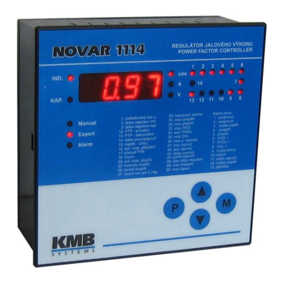
Page 9: Front Panel
Novar 1xxx KMB systems 1.8 Front Panel The front panel consists of a numeric display, indication LEDs and control keys. Figure 1.1: Front Panel 1.9 Numeric Display Information shown on the numeric display can be divided into 3 main data groups: •... - Page 10 Novar 1xxx KMB systems Figure 1.2: Instantaneous value display – structure main branch cos branch current Ieff branch voltage Iact Ueff branch dPre Irea Temp dIrea Acos THDI THDU mincos harI harU APac … harI maxPac … harU APre harI...
-
Page 11: Cos Branch
Novar 1xxx KMB systems Pressing the M button switches to the relevant subbranch: to the branch of power factors, power, and temperature while displaying COS (further as COS Branch), to the current branch while displaying Ieff (further as A Branch) or to the voltage branch while displaying Ueff (further as V Branch). Again, you can move up and down the branch using the ▲, ▼... -
Page 12: A Branch
Novar 1xxx KMB systems 3. Maximum temperature maxTemp The temperature moving average maximum value. The moving window depth is fixed at 1 minute. The above described recorded values can be cleared, each group separately – when clearing a value, all other values in the same groups are cleared too. Clearing values is explained in the Editing chapter further down the manual. -
Page 13: Branch
Novar 1xxx KMB systems Table 1.3: List of Measurement Quantities – A Branch abbreviation symbol quantity unit Iact Instantaneous active current fundamental harmonic component A / kA * (active). Irea Instantaneous reactive current fundamental harmonic component A / kA * (reactive);... -
Page 14: Controller Parameters
Novar 1xxx KMB systems 1.9.1.3 Controller Parameters You can view controller parameters by pressing the P button (parameters). First the parameter number shows momentarily and then its value does. The parameter number flashes momentarily every five seconds for better orientation. -
Page 15: Novar 10Xx Controllers
Novar 1xxx KMB systems Exception: In the Manual mode the parameter values cannot be viewed. Instantaneous output values are displayed on pressing button P (parameters) — see description further below. 1.9.2 Novar 10xx Controllers Novar1005, 1007, 1005D and 1007D controllers are equipped with 3 buttons only – instead M- and P- buttons, they features one ►- button. -
Page 16: Output State Indications
Novar 1xxx KMB systems 1.10.1 Output State Indications The array of LEDs at the top right of the front panel show the current state of output relays. Each LED is assigned a number from 1 to 14, and if lit, they indicate closed contacts of the corresponding output relay. -
Page 17: Installation
Novar 1xxx KMB systems 2. Installation 2.1 Physical Instruments designed for a distribution board panel are mounted into a cutout of required size. The instrument’s position must be fixed with locks. The Novar1005D and theNovar1007D are designed for mounting on a DIN-35 bar. -
Page 18: S400" Version Controllers
Novar 1xxx KMB systems Fig. 2.2 : Novar1214 Controller – Connectors Serial / vers.: Product. date : ÷ 275 VAC, 7VA, ÷ 67 Hz IP 4X Made in Czech Republic 10 11 12 13 14 ALARM Tx GND RS 232/485 100÷275 VAC... -
Page 19: Novar 1005D / 1007D Controllers
Novar 1xxx KMB systems Fig. 2.4 : Novar 1007 Controller – Connector NOVAR 1005 1007 U~ 80÷275VAC,43÷67Hz Příkon 5 VA (7) (8) (1007) 2.2.1.4 Novar 1005D / 1007D Controllers The power supply is connected to terminals 16 (L1) and 18 (N). Power supply voltage needs to be externally protected ( see chapter Protection below ). -
Page 20: Measurement Current
Novar 1xxx KMB systems to 67 Hz of either phase or line voltage. In basic connection phase L1 goes to terminal L (7) and neutral wire to terminal N/L (9). The measurement voltage must be protected externally. If the measurement voltage is identical with power supply voltage, they can share a circuit breaker. -
Page 21: Novar 10Xx Controllers
Novar 1xxx KMB systems Despite of standard version, the relays’ common contacts are connected to additional terminals 33, In case of DC voltage for supplying of contactors, installation of suppression 2A/600V diodes directly at contactors´s coils is strongly recommended. Furthermore, note lower maximum current load of the controller outputs at such case ( see technical parameters table). -
Page 22: Ethernet (Ieee802.3) Interface
Novar 1xxx KMB systems Table 2.2: communication line signal configuration signal terminal DATA A DATA B GND/C The interface allows connecting up to 32 instruments at a distance up to about 1 kilometre. Recommended cable is shielded twisted metallic double pair. Use one pair for DATA A and DATA B signals and the second pair for GND/C signal interconnection. -
Page 23: Putting In Operation
Novar 1xxx KMB systems 3. Putting in Operation 3.1 First Use The controller comes preset to default values as shown in Table 4.1. On powerup, display test runs first. The display momentarily shows • type of controller (e.g. N214 N214... -
Page 24: Automatic Section Power Recognition Process
Novar 1xxx KMB systems APnn APnn APnn APnn (Automatic Phase detection, nn 1. step number in format ... attempt number) L1-0 L1-0 L1-0 L1-0 2. attempt result, e.g. (see Table 4.4 for connection methods) If the controller measures identical values repeatedly in each attempt, it considers the connection detected and quits carrying out further steps. - Page 25 Novar 1xxx KMB systems For the controller to be able to start the automatic section power recognition process, the following conditions must be met: • controller automatic operation is not disabled (i.e. the Manual LED is dark) • controller is in control mode, i.e. the numeric display mode is Measurement •...
- Page 26 Novar 1xxx KMB systems If the automatic section power recognition process can not be completed successfully or none of the sections recognized is capacitive, flashing is shown on the numeric display and the Alarm signal is activated at the same time. In such an event, it is necessary to enter each section’s value...
-
Page 27: Operation
Novar 1xxx KMB systems 4. Operation 4.1 Setup To achieve optimum compensation in accordance with character of the load controlled, the controller has a number of parameters that govern its operation. Table 4.1 shows a list of the parameters. The following chapters describe each parameter, its meaning and how it can be edited. -
Page 28: Parameter 01/07 - Target Power Factor
Novar 1xxx KMB systems Ed=0 Ed=0 Ed=0 Ed=0 ..… edit disabled Ed=1 Ed=1 Ed=1 Ed=1 ..… edit enabled – parameters can be edited, recorded measurement values can be cleared If Parameter Edit is locked, you can unlock it using the following procedure, which is similar to editing the controller’s parameters:... -
Page 29: Parameter 03/09 - Overcompensation Control Time
Novar 1xxx KMB systems • the difference between reactive power instantaneous value in the power system and optimum value, which corresponds to the target power factor setting (= control deviation), is just equal to the smallest section power (C/k If the parameter value is set to say 3.0 and the above mentioned conditions are met in the power system, the controller calculates optimum compensation and carries out control intervention every 3 minutes. - Page 30 Novar 1xxx KMB systems Table 4.1: Novar10xx/11xx/12xx Controller Parameters name range step default comment see Enable / Disable Parameter Editing parameter edit enable/disable 0 / 1 — target power factor (metering rate 0.80 L ÷ 0.80 C 0.01 0.98 L No “L”: control time reduction by squared...
-
Page 31: Parameter 05/11 - Offset Power
Novar 1xxx KMB systems Ranges and units as in Table 4.7 alarm thresholds: undervoltage, — — — not displayed if the alarm not set up ÷ overvoltage, THDI, THDU, CHL, number of connections and temperature Indicates current state of alarm. -
Page 32: Parameter 06 - Metering Rate 2 Operation
Novar 1xxx KMB systems So if, for example, an offset control is required due to a front-end capacitor, you must specify positive offset power value. The controller will then intentionally undercompensate at its connection node just by the size of the specified offset power value. -
Page 33: Parameters 15, 16 - Type Of Measurement Voltage And Connection Configuration
Novar 1xxx KMB systems 4.1.10 Parameters 15, 16 – Type of Measurement Voltage and Connection Configuration U=LN U=LN U=LN U=LN Parameter 15 determines if the measurement voltage connected is phase (phase-neutral, U=LL U=LL U=LL U=LL default value) or line (phase-phase, ). -
Page 34: Setting Type Of Connection Configuration If Measuring At Power Supply Transformer's Opposite Sides
Novar 1xxx KMB systems 4.1.10.1 Setting Type of Connection Configuration if Measuring at Power Supply Transformer’s Opposite Sides If the measurement current signal is from the power supply transformer’s side which is opposite to measurement voltage signal side, the transformer phase angle is conclusive for correct parameter 15 setting. -
Page 35: Parameter 17 - Metering Voltage Transformer (Vt) Turns Ratio
Novar 1xxx KMB systems If in doubt about correctness of determining the type of connection, experimental validation is convenient: after automatic connection configuration detection process you can usually compare the power factor value shown by the controller with information on the billing electricity meter (ratio of revolutions of active and reactive electricity meters). -
Page 36: Parameter 21, 22 - Switching Program, Selection Of Linear Switching Mode And Smallest
Novar 1xxx KMB systems 1 1 1 1 If the parameter is set to , the controller carries out the automatic section recognition power process every time the controller is powered up, irrespective of the section values having been recognized before or not. -
Page 37: Parameter 23 - Number Of Capacitors
Novar 1xxx KMB systems The smallest capacitor nominal value is to be taken from its identification plate or checked by measuring its phase current with a clamp-on ammeter. Table 4.4 shows phase current values for the most usual three-phase compensation capacitors. -
Page 38: Parameter 26 - Fixed Sections, Switching Cooling And Heating, Alarm
Novar 1xxx KMB systems Capacitive sections are shown as positive, inductive sections as negative values. If a section’s current is not known (for example because of successful completion of the automatic section power recognition process), the ---- value is shown. In such an event, as well as in the event of section current zero value, the controller does not use the corresponding control output. -
Page 39: Switching Cooling And Heating
Novar 1xxx KMB systems 4.1.17.2 Switching Cooling and Heating The two highest outputs can be set to switch cooling (fan) and heating, for example as follows: 14-F 14-F 14-F 14-F ..output 14 set to switch cooling (fan) 13-H 13-H 13-H 13-H ..output 13 set to switch heating... - Page 40 Novar 1xxx KMB systems • alarm actuation Table 4.5: Alarm – Indication condition description minimum delay of activation / deactivation 1 undercurrent current at metering current transformer’s secondary 5 / 5 seconds side under minimum measurement current 2 overcurrent current at metering current transformer’s secondary immediately side over 120% of nominal value setting (6 A / 1.2...
-
Page 41: Alarm Indication
Novar 1xxx KMB systems 4.1.19.1 Alarm Indication In order to indicate nonstandard compensation conditions, the instruments feature an Alarm LED in the front panel and an Alarm relay potential-free contact accessible at a connector in the rear panel. At Novar 10xx models, that are not equipped with the dedicated Alarm relay, it is possible to use any of highest two outputs for Alarm signalling ( see parameter 26). -
Page 42: Parameters 31 Through 37 - Alarm Indication/Actuation Limits
Novar 1xxx KMB systems 4.1.20 Parameters 31 through 37 – Alarm Indication/Actuation Limits If indication or actuation from a condition shown in Table 4.7 is set up, you also need to specify the relevant quantity’s limit value exceeding which triggers the indication or actuation. The table shows parameter numbers where the limits are stored, limit setup ranges, and limit default values. -
Page 43: Parameter 40 - Alarm Status
Novar 1xxx KMB systems 4.1.21 Parameter 40 – Alarm Status If an indication function from a nonstandard condition is set (see description of parameter 30 – alarm setting), you can view alarm’s current status in the side branch of parameter 40. -
Page 44: Parameter 55 - Power System Frequency
The communication rate (parameter 51) can be set to one of the values: 4800, 9600, 19200 Bd. The standard communication program uses a proprietary communication protocol, “KMB”. The P0 P0 protocol is set as default in parameter 52, as . -
Page 45: Parameter 58 - Temperature Display °C / °F
Novar 1xxx KMB systems At the default setting shown above, the quantities Acos, APac, and APre contain the values of average power factor, average active power, and average reactive power, respectively, for the last 7 days. Analogously the quantities mincos, maxPac, maxPre, and maxdPre contain the minimum values of 1-... -
Page 46: Section Value Accurization
Novar 1xxx KMB systems Example: A compensation capacitor with a nominal value of 5 kvars is permanently connected to a power transformer, which is before the controller CT. It is required to control the target power factor of 1.00, which is to be registered by an electricity meter, measuring whole transformer load. The controller can then be set as follows: •... -
Page 47: Faulty Section Indication And Disablement
Novar 1xxx KMB systems 4.3 Faulty Section Indication and Disablement In the alarm setting (parameter 30) you can choose alarm indication or actuation from detecting a faulty section (section error). If at least one of these functions has been set, the controller continually checks reactive power changes in the power system during the control process as the sections are connected and disconnected and compares them with each section’s power recorded. -
Page 48: Basic Choke Compensation
Novar 1xxx KMB systems After controller initialization, parameter 27 value is not specified, so compensation by choke is disabled by default. 4.4.1 Basic Choke Compensation Usually, one or few chokes only are installed in combined compensation systems. To reach sufficient precision of power factor control, a suitable set of capacitors are added to the choke(s) and controller freely combines both the chokes and the capacitors as needed to reach preset target power factor. -
Page 49: Control Interruption
Novar 1xxx KMB systems 4.5 Control Interruption If the controller is in the automatic control mode (not in the Manual mode), one of the values measured is shown on the numeric display (Measurement display mode) and the controller carries out control process based on the values measured and parameter settings. -
Page 50: Controller Initialization
Novar 1xxx KMB systems While holding button M pressed down you can connect or disconnect a section using buttons ▲and ▼ and watch the controller’s response to the change of condition. Each button press connects or disconnects one compensation section, always the one with the smallest value (exception: in the linear switching mode the order of connecting/disconnecting is specified in description of parameter 21). - Page 51 Novar 1xxx KMB systems Ic..capacitor current [ A ] U..capacitor voltage [ V ] Zc... capacitor impedance f..frequency [ Hz ] C... capacitor capacity [ F ] If the voltage is distorted, the current flowing through a capacitor forms as the sum of current harmonic component vectors ∑...
- Page 52 Novar 1xxx KMB systems shows CHL factor values for a few selected scenarios of harmonic distribution at fundamental harmonic component nominal value. Table 4.9: Examples of CHL factor values for selected distributions of voltage harmonic components voltage harmonic component levels [ % ] [ % ] Example 3 (CHL = 133%) corresponds to voltage harmonic distortion limits as specified in EN 50160.
-
Page 53: Text Messages
Novar 1xxx KMB systems 4.10 Text Messages In the measurement value display mode, a text message may appear in some situations instead of the instantaneous power factor value. Table 4.10 shows a list of these messages. Table 4.10: List of text messages... -
Page 54: Novar1312, Novar1312-3, Novar1005T Description
Novar 1xxx KMB systems 5. Novar1312, Novar1312-3, Novar1005T Description 5.1 Basic Operation These Power Factor Controllers allow optimized control of rapid reactive power compensation at up to 25 control interventions per second. It features transistor outputs to drive thyristor switches and, in case of the 1312 and the 1312-3 models, relay outputs too to connect conventional contactors or to switch cooling and heating, respectively. -
Page 55: History Of Firmware Versions
Novar 1xxx KMB systems 5.5 History of Firmware Versions version date of release note 3/2007 - basic version 10/2008 - maximum control rate increased 4/2014 - THD & CHL alarm behaviour correction at voltage fail 6/2014 - MaxTHD & MaxCHL values correction... -
Page 56: Novar-1005T
Novar 1xxx KMB systems Fig 5.1 : Novar-1312 – connectors Fig. 5.2 : Novar-1312-3 – connectors NOVAR 1312-3 / 485 E NOVAR 1312 / 232 485 Výr.č./verze.: Serial / vers.: Datum výroby : Product. date : ÷ ÷ ÷ 275 VAC, 7VA, ÷... -
Page 57: Relay Outputs
Novar 1xxx KMB systems 5.6.3 Relay Outputs The Novar-1312 and the Novar-1312-3 models have additional 2 output relays : R13 and R14. The relays’ contacts go to terminals 33, 34. Relays’ common contacts are internally connected to power supply terminal 3 (L) — when an output relay contact closes, power supply voltage appears at the corresponding output terminal. -
Page 58: Setup
Novar 1xxx KMB systems Slow control process has to respect limitations from the compensation sections’ contactors’ parameters and service life. Phase measurement takes place once a second and control phase timing, which can only repeat every five seconds, is determined by the control deviation evaluated and control period specified. -
Page 59: Control Operation At The Highest Control Rate
Novar 1xxx KMB systems It is because in some situations, the switching rate and reconnection delay time must be adopted to the fast-discharge resistors’ power rating (these resistors are required for proper power thyristor switch operation if compensation capacitor overcharging takes place). - Page 60 Novar 1xxx KMB systems Table 5.1: Novar1312 / Novar1312-3 / Novar1005T Parameters name range step default comment see Enable / Disable Parameter Editing parameter edit enable/disable 0 / 1 — target power factor (metering rate 0.80 L ÷ 0.80 C 0.01...
- Page 61 Novar 1xxx KMB systems Ranges and units as in Table 4.7 alarm thresholds: undervoltage, — — — not displayed if the alrm not set up ÷ overvoltage, THDI, THDU, CHL, number of connections and temperature Indicates current state of alarm.
-
Page 62: Novar-1414 Description
Novar 1xxx KMB systems 6. Novar-1414 Description 6.1 Basic Operation Despite of other models, this controller model has three current measurement inputs ( one voltage measurement input only stays unchanged ). It is capable to measure load of all three phases and evaluates three-phase power factor for the control. -
Page 63: A Branch
Novar 1xxx KMB systems Tab. 6.2 : List of the Novar-1414 Measurement Quantities – Cos Branch abbreviation symbol quantity unit cos1 Instantaneous power factor of phase L1 cosI cosI cosI cosI cos2 Instantaneous power factor of phase L2 cos2 cos2... -
Page 64: Communication
Novar 1xxx KMB systems Fig. 6.1 : Novar 1414 Controller – connectors Serial / vers.: Product. date : ÷ 275 VAC, 7VA, ÷ 67 Hz IP 4X Made in Czech Republic 10 11 12 13 14 ALARM Tx GND RS 232/485 100÷275 VAC... - Page 65 Novar 1xxx KMB systems current inputs are detected. After the process is finished, you can check their values in the parameter It is strongly recommended to use the connection detection process for the parameter 16 setup. If it is not possible, you can use individual single-phase power factor values cos1, cos2 and cos3 for their...
-
Page 66: Wiring Examples
Novar 1xxx KMB systems 7. Wiring Examples Novar1007 – installation... - Page 67 Novar 1xxx KMB systems Novar1007D – installation...
- Page 68 Novar 1xxx KMB systems Novar1106 – installation...
- Page 69 Novar 1xxx KMB systems Novar1114 – installation...
- Page 70 Novar 1xxx KMB systems Novar1206 – installation, low voltage measurement...
- Page 71 Novar 1xxx KMB systems Novar1214 – installation, high voltage measurement...
- Page 72 Novar 1xxx KMB systems Novar1114/S400 – installation...
- Page 73 Novar 1xxx KMB systems Novar-1214/S400 – installation, controller and contactors supllied from DC...
- Page 74 Novar 1xxx KMB systems Novar1312 – installation, hybrid system with both thyristor switches and contactors...
- Page 75 Novar 1xxx KMB systems Novar-1005T – installation...
- Page 76 Novar 1xxx KMB systems Novar1414 – installation, low voltage measurement...
- Page 77 Novar 1xxx KMB systems Novar – RS-485 Communication Link Connection NOVAR-206 214 / 232 485 Výr.č./verze.: Datum výroby : Nap.: 230 V~50/60 Hz Přík.: 10VA IP 4X Made in Czech Republic 10 11 12 13 14 ALARM NOVAR-206 NOVAR-214...
-
Page 78: Technical Specifications
Novar 1xxx KMB systems 8. Technical Specifications Adjustable Parameters parameter Novar Model 1005 / 1007 1106 / 1114 1206 / 1214 / 1312 1005D / 1007D 1414 1312-3 1005T power factor desired 0.80 ind. through 0.80 cap. connection time (maximum value, 5 to 1 200 seconds 1 ÷... - Page 79 1/32 maximum node–to–node distance 30 metres / 1200 metres data transfer protocol KMB / Modbus RTU Operating Conditions working environment class C1 in compliance with IEC 654-1 operating temperature -40° ÷ +60°C...
-
Page 80: Maintenance, Troubleshooting
In the event of the product’s breakdown, you have to return it to the supplier at their address. supplier: manufacturer: KMB systems, s.r.o. 559 Dr. M. Horákové 460 06, Liberec 7 Czech Republic website: www.kmbsystems.eu The product must be packed properly to prevent damage in transit.
Need help?
Do you have a question about the NOVAR-1 S400 Series and is the answer not in the manual?
Questions and answers