Table of Contents
Advertisement
Quick Links
Advertisement
Table of Contents

Subscribe to Our Youtube Channel
Related Manuals for CIAT Vectic


Summary of Contents for CIAT Vectic
- Page 1 Air-air units NA 17.91 G 06 - 2023 Electronic control User manual...
-
Page 2: Table Of Contents
CONTENTS 1 - GENERAL DESCRIPTION ..................................3 1.1. VecticGD graphic terminal .................................3 1.2. TCO user terminal (optional) ................................3 1.3. Sensors ......................................4 1.4. c.pCOe expansion cards (optional) ..............................4 1.5. Driver EVDEVO (optional) .................................4 1.6. SMALL board (optional)..................................5 1.7. BMS communication ..................................5 1.8. Communication in a SHRD shared network ............................6 1.9. -
Page 3: General Description
1 - GENERAL DESCRIPTION The Vectic control is an electronic module with microprocessor ● Rotary heat exchanger. Wheel speed with on/off control or variable designed for the control and supervision of air-air units. control. This control consist of a control board, sensors, a VecticGD graphic ●... -
Page 4: Sensors
1 - GENERAL DESCRIPTION 1.3. Sensors intended for the suction probe of circuit 2 can be used to connect this probe. Unit with 1 circuit Optional sensors connected, in series, on the Field-bus: ● RS485 ambient temp. probe (1 to 4 probes connected in series): Outdoor temperature probe Outdoor fan - When the unit needs the outdoor humidity probe (with enthalpic... -
Page 5: Small Board (Optional)
This open standard enables the connection ABOUND HVAC Performance is a remote supervision solution and integration of devices in building dedicated to monitoring and controlling several CIAT machines automation applications both at the in real time. commercial and at the residential level. -
Page 6: Communication In A Shrd Shared Network
65,2 Kbit/s; maximum network length: 500 m. ambient temperature or ambient temperature + humidity, outdoor temperature, outdoor humidity and CO air quality. For more detailed information refer to the manual of the Vectic control (NA1671G). ● Extended Master/Slave: It includes “Master/Slave” functionalities and the Master unit provides ambient temperature setpoints to the other units. -
Page 7: User Interfaces
2 - USER INTERFACES 2.1. VecticGD graphic terminal (standard) Features Keys and combinations (quick guide) ● LCD FSTN display (132 x 64 pixel), backlit in blue. Function ● The screen provides detailed explanations of control in easy to Alarm There is/are active alarm(s) if the key is illuminated understand English. -
Page 8: Tco User Terminal (Optional)
2 - USER INTERFACES 2.2. TCO user terminal (optional) Features Keys and combinations (quick guide) ● LCD display, backlit in blue. Function ● Built-in temperature sensor. Allows the operating mode to be Operating ● Clock and Scheduling. selected: HEATING, COOLING, AUTO or mode VENTILATION (only if selection by panel is activated) -
Page 9: Menu Structure In The Vecticgd Graphical Terminal
3 - MENU STRUCTURE IN THE VECTICGD GRAPHICAL TERMINAL Main menu Access level Manufacturer menu 01.Unit Status Level 1 a.Unit Config. 02.Unit On/Off Level 1 b.Defrost Config. 03.Setpoint Level 1 c. Compressor Config. 04.Summer/Winter Level 1 d. Regulation Config. 05.Clock/Scheduler Level 1 e.Safety Config. -
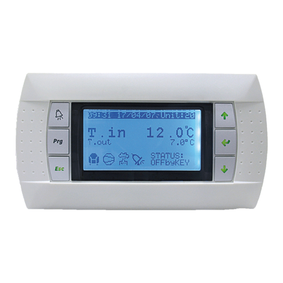
Page 10: Information About The Unit Status
4 - INFORMATION ABOUT THE UNIT STATUS Initial screen Unit: This indicates the OFF/ON status: On Turned on. When the VecticGD terminal is switched on, the screen below shows this information: Off Turned off . Remote Off If enabled for a remote shutdown. Off by phase If the unit is shut down by Scheduling. -
Page 11: Starting / Stopping The Unit
5 - STARTING / STOPPING THE UNIT There are diff erent procedures for starting / stopping the unit (On/Off ): • By keyboard (from the terminal): Note: See the diff erent types of schedules in the chapter of “Scheduling”. This procedure is always valid. If the unit is stopped from the terminal, it cannot be started using any of the other procedures. -
Page 12: Setpoints Selection
6 - SETPOINTS SELECTION The control of the ambient temperature is carried out by starting up VS Setpoint of the auxiliary hot water coil in COOLING mode the unit: compressors and/or backup component (electrical heater, VW Setpoint of the auxiliary hot water coil in HEATING mode water coil, etc.). -
Page 13: Selection Of The Operating Mode
7 - SELECTION OF THE OPERATING MODE There are diff erent procedures for the selection of the operating * By indoor temperature: The unit changes from operation in COOLING mode to HEATING mode or vice versa depending mode: on the temperature measured by the ambient (or return) air •... -
Page 14: Cooling Operating Mode (Summer)
7 - SELECTION OF THE OPERATING MODE 7.1. COOLING operating mode (summer) 7.2. HEATING operating mode (winter) The control will compare the temperature reading of the ambient (or The control will compare the temperature reading of the ambient (or return) air probe with the value set by the COOLING setpoint and return) air probe with the value set by the HEATING setpoint and with the value of the control band. -
Page 15: Time Scheduling
8 - TIME SCHEDULING 8.1. Scheduling: VecticGD terminal The VecticGD graphical terminal incorporates a scheduler with - COMFORT: standard setpoint of the unit. possibility of 3 diff erent programs. It allows to choose for each day - ECONOMY: setpoint further away from the comfort point, used of the week one of these 3 programs. - Page 16 8 - TIME SCHEDULING The regulation setpoint and safety limit setpoint are established PH15 on the screen PH09 (summer) and on the screen PH10 (winter): Schedule with setpoint * Indoor set.: setpoint for the time slots. change (Winter) CONFORT Set 21.0ßC * Limit set.: safety limit setpoint outside the time slots.
-
Page 17: Scheduling: Tco Terminal
8 - TIME SCHEDULING 8.2. Scheduling: TCO terminal This type of schedule does not appear in the screen selection. With the TCO terminal enabled (optional), the schedule programming To activate it press the key for a few seconds. Access is gained of this terminal can be done. - Page 18 8 - TIME SCHEDULING It will be necessary to defi ne a minimum of two slots for each day, If it is desired to continue with the scheduled programme, since only the initial time is established is established for each slot, must be pressed with the terminal on the initial programming display and not the ending time.
-
Page 19: Display Of The Inputs / Outputs Status
In this group of screens 15. Versions from the MAIN MENU, the The second screen of this menu shows the main features of the Software version installed on the control board is provided. hardware. SOFTWARE HARDWARE Vectic Contro1 Board type: uPC3 Board size: Medium Version: 16.2.0... -
Page 20: Safety Functions
11 - SAFETY FUNCTIONS 11.1. Defrosting function When the unit is working in HEATING mode, the defrosting of the - The optional backup device incorporate by the unit can be enabled: electrical heaters, hot water coil, gas burner or boiler. outdoor coils is performed by cycle inversion in order to remove any ice which has accumulated on them. -
Page 21: R-454B Refrigerant Leak Detector (Standard)
11 - SAFETY FUNCTIONS 11.4. R-454B Refrigerant leak detector (standard) Due to the A2L category of R-454B refrigerant (lightly fl ammable), • The parameter “%LFL reset” (by default, 10%) allows to adjust the units that incorporate this refrigerant require the installation of a the percentage of LFL (Lower Flammability Limit) below which the leak detector. -
Page 22: Compressor Lock
11 - SAFETY FUNCTIONS 11.6. Compressor lock 11.8. High or low indoor temperature safety In the event of a power cut-off for a period longer than 2 hours, The control indicates an alarm event when the indoor temperature the compressors will be locked. The unit must remain 8 hours (return or ambient) drops bellow 15ºC or exceeds 40ºC. -
Page 23: Alarms
12 - ALARMS 12.1. Alarm display On the VecticGD terminal: On the TCO terminal (optional): If the icon appears on the TCO terminal display, there is/are There is/are active alarm(s) if the key is illuminated red. active alarm(s). By pressing the key once, the description of the fi rst alarm will be shown. -
Page 24: Alarm List
12 - ALARMS 12.3. Alarm list Controlled alarms Unit Aff ected circ. Reset Timing Actuation Alarm level VecticGD TCO Add. shutdown shutdown Type (**) Thermal protection of compressors and 1 (2 with Auto (*) No Shutdown of circuit 1 AL01 outdoor fan(s) of circuit 1 manual reset) Thermal protection of compressor of... - Page 25 12 - ALARMS Controlled alarms Unit Aff ected circ. Reset Timing Actuation Alarm VecticGD TCO Add. shutdown shutdown Type level (**) Only indication (safety into the burner/boiler) Yes, Gas burner or boiler Auto (*) Yes, 4 s Unit / compressor shutdown 3 or 2 AL24 AL24...
- Page 26 12 - ALARMS Controlled alarms Unit Aff ected circ. Reset Timing Actuation Alarm VecticGD TCO Add. shutdown shutdown Type level (**) Supply plug-fan addr.22 without Auto Only indication AL47a communication Supply plug-fan addr.23 without Auto Only indication AL47b communication Supply plug-fan addr.24 without Auto Only indication AL47c...
- Page 27 12 - ALARMS Controlled alarms Unit Aff ected circ. Reset Timing Actuation Alarm VecticGD TCO Add. shutdown shutdown Type level (**) Failure in the return damper not closed Manual Yes, 160 s Only indication AL73 (c.pCOe expansion card address 9) Failure of the supply damper not open in Yes, 30 s Auto...
-
Page 28: Alarm Levels With "Back-Up
12 - ALARMS Controlled alarms Unit Aff ected circ. Reset Timing Actuation Alarm VecticGD TCO Add. shutdown shutdown Type level (**) 1 (2 after Alarm driver Eliwell address 71 Manual No Shutdown of circuit 1 AL111 delay) 1 (2 after Alarm driver Eliwell address 72 Manual No Shutdown of circuit 2... -
Page 29: List Of Control Parameters With "Access Level 1
Important: All parameters of level “1” are visible to the fi nal user without any password. Parameters with levels of access “2” and “3” are protected by passwords and they can be found in the complete brochure of the Vectic control (NA1671G). - Page 30 13 - LIST OF CONTROL PARAMETERS WITH "ACCESS LEVEL 1" Parameters of “Unit Status” (...continuation) 01.Unit Status Add. Screen Parameter Description of the parameter Value Min. Max. UOM Type NUM_WO_DIG_3 Work order number of the unit (digit 3) Analog. R Analog.
- Page 31 13 - LIST OF CONTROL PARAMETERS WITH "ACCESS LEVEL 1" Parameters of “Summer/Winter” 04.Summer/Winter Add. Screen Parameter Description of the parameter Value Min. Max. UOM Type Procedures for the selection of the COOLING/HEATING mode: 0: by keyboard 1: remote (by digital input) FC01 SEL_FRIO_CALOR 2: auto...
- Page 32 13 - LIST OF CONTROL PARAMETERS WITH "ACCESS LEVEL 1" Parameters of “Clock/Scheduler” (...continuation) 05.Clock/Scheduler Add. Screen Parameter Description of the parameter Value Min. Max. UOM Type Stop minute of slot 3 - program 2 Integer R/W 97 PH05 M_PAR_2C PH06 H_ARR_3A Start-up hour of slot 1 - program 3...
- Page 33 13 - LIST OF CONTROL PARAMETERS WITH "ACCESS LEVEL 1" Parameters of “Clock/Scheduler” (...continuation) 05.Clock/Scheduler Add. Screen Parameter Description of the parameter Value Min. Max. UOM Type PH13a Scheduler_1.VacationsSched[0].EndMonth Last month of the period Integer R/W Unit status during the holiday period (0=OFF; 1=PROTECTION; PH13a Scheduler_1.VacationsSched[0].UnitStatus Integer R/W 2=ECONOMY;...
- Page 34 13 - LIST OF CONTROL PARAMETERS WITH "ACCESS LEVEL 1" Parameters of “Input/Output” 06.Input/Output Add. Screen Parameter Description of the parameter Value Min. Max. Type TEMP_RET Display of the return air temperature -99.9 99.9 °C Analog. R TEMP_EXT Display of the outdoor air temperature -99.9 99.9 °C...
- Page 35 13 - LIST OF CONTROL PARAMETERS WITH "ACCESS LEVEL 1" Parameters of “Input/Output” (...continuation) 06.Input/Output Add. Screen Parameter Description of the parameter Value Min. Max. UOM Type I05c T_P_LP_C1_AIN06 Display of the low pressure transducer of circuit 1 -99.9 99.9 Analog.
- Page 36 13 - LIST OF CONTROL PARAMETERS WITH "ACCESS LEVEL 1" Parameters of “Input/Output” (...continuation) 06.Input/Output Add. Screen Parameter Description of the parameter Value Min. Max. UOM Type I08a DIN_OFF_4ET Status of digital input 23: disconnection of 4 compressor stages Digital R I08a DIN_OFF_RES Status of digital input 24: disconnection of electrical heaters...
- Page 37 13 - LIST OF CONTROL PARAMETERS WITH "ACCESS LEVEL 1" Parameters of “Input/Output” (...continuation) 06.Input/Output Add. Screen Parameter Description of the parameter Value Min. Max. Type REACTIVE_POWER_TOTAL Reading of the energy meter: total reactive power -999.9 999.9 kVAR Analog. R REACTIVE_ENERGY Reading of the energy meter: equivalent reactive energy 4294967295 kWhR Integer R...
- Page 38 13 - LIST OF CONTROL PARAMETERS WITH "ACCESS LEVEL 1" Parameters of “Input/Output” (...continuation) 06.Input/Output Add. Screen Parameter Description of the parameter Value Min. Max. UOM Type I08cr CR_DIN01_DEBUG Status of digital input: remote On/Off Digital R I08cr CR_DIN02_DEBUG Status of digital input: high pressure switch of the recovery circuit Digital R I08cr CR_DIN03_DEBUG...
- Page 39 13 - LIST OF CONTROL PARAMETERS WITH "ACCESS LEVEL 1" Parameters of “Alarms History” 11.Alarms History Add. Screen Parameter Description of the parameter Value Min. Max. UOM Type AlrmLogsIdx Index to sort alarms Integer R AlrmLogHour Time to which the alarm log value is referred by the AlrmLogsIdx index Integer R AlrmLogMinute Minute to which the alarm log value is referred by the AlrmLogsIdx index Integer R...
-
Page 40: Conections
14 - CONECTIONS 14.1. Main control board FieldBus1 FieldBus2 VecticGD Vectic / BMS FieldBus2 / BMS configuration Display port1 / BMS EEV1 Field bus Display port2 Ethernet EEV2 +5VR GND+Vdc Control BMS card Stand-by Micro Analog inputs outdoor fan circuit 1: electronic fan (standard in PJ units) -
Page 41: Connection Of Terminals To The Control Board
RJ12 Rx+/Tx+ 0,8 m FieldBus1 Shielding FieldBus2 / BMS VecticGD terminal Display port1 Vectic / BMS Display port2 Ethernet +5VR GND+Vdc FieldBus1 ● From 200 to 500 metres, it is necessary to use the TCONN bypass FieldBus2 / BMS cards, AWG 20/22 shielded cable with 1 twisted pair and external 20...30Vdc (150 mA) power supply. -
Page 42: Connection Of The Basic C.pcoe Expansion Modules To The Control Board (Optional)
14 - CONECTIONS 14.3. Connection of the Basic c.pCOe expansion modules to the control board (optional) Address Ext Baud Prot 19.2 K 9.6 K 38.4 K CAREL 19.2 K 57.6 K Modbus 9.6 K 38.4 K CAREL 57.6 K Modbus Address Baud Prot... -
Page 43: Connection Of The Enhanced C.pcoe Expansion Module To The Control Board (Optional)
14 - CONECTIONS 14.4. Connection of the Enhanced c.pCOe expansion module to the control board (optional) Address Ext Baud Prot driver 19.2 K 19.2 K 9.6 K 38.4 K CAREL 9.6 K 57.6 K Modbus 38.4 K CAREL 57.6 K Modbus Address Baud... -
Page 44: Connection Of The Small Board To The Control Board (Optional)
14 - CONECTIONS 14.5. Connection of the SMALL board to the control board (optional) J1 - power supply 230 Vac RX-/TX- +Vdc RX+/TX+ J2 - probe power supply +5 Vref SMALL Return T probe of zone 1 (optional) shield Return T probe of Vout board zone 2 (optional) -
Page 45: Serial Connection Of Rs485 Probes To The Field-Bus Of The Control Board (Optional)
● 1 to 4 probes of ambient temperature or temperature + humidity. ● Enthalpy probes on the mixing air and the supply air for calculation of the cooling and heating capacities. FieldBus1 FieldBus2 Vectic / BMS FieldBus2 / BMS configuration... -
Page 46: Technical And Electrical Characteristics
15 - TECHNICAL AND ELECTRICAL CHARACTERISTICS Main CPU board installed in the unit’s electric panel, which allows data to be input, treated by the microcontroller and the operation of the unit to be managed completely. The program and the parameters are stored in non-volatile memory, there by ensuring their storage even in the case of a power failure (without needing an auxiliary coil). - Page 47 15 - TECHNICAL AND ELECTRICAL CHARACTERISTICS c.pCOe expansion modules TECHNICAL CHARACTERISTICS Storage conditions -40T70 ºC; %HR 90 non-condensing Operating conditions -20T70 ºC; %HR 90 non-condensing Protection index IP40 only on the front panel Environmental pollution Level 3 Classifi cation according to protection against electric shocks To be incorporated in class I and/or II appliances Period of electric stress across the insulating parts Long...
- Page 48 15 - TECHNICAL AND ELECTRICAL CHARACTERISTICS VecticGD terminal TECHNICAL CHARACTERISTICS OF THE DISPLAY Type FSTN graphic Back-lighting Blue LED (controlled using software) Resolution 132 x 64 pixel TECHNICAL CHARACTERISTICS OF THE POWER SUPPLY Power supply through the telephone cable or external source 18/30 Vdc protected Voltage by an external 250 mAT fuse Maximum power input...
-
Page 49: Ambient Probe
15 - TECHNICAL AND ELECTRICAL CHARACTERISTICS 15.1. Ambient probe Wall version (DPW) ● Tighten the screw on the bracket to fasten. Case index of protection: IP30 Sensor index of protection: IP30. Assembly and setting instructions ● This probe must be fi xed to the panel or the wall of the room to be conditioned, at ca. -
Page 50: Air Quality Probe 4
15 - TECHNICAL AND ELECTRICAL CHARACTERISTICS Duct-mounted ● Close the sensor by turning the cover clockwise (fi g.4). This version can be connected to the air duct in these two ways: ±0.3 3.54 “ ±0.11 Ø > 13mm Ø > 0.51“ (fi... -
Page 51: Troubleshooting
16 - TROUBLESHOOTING ● The unit does not switch on (the power LED on the main board is - Check that the probe capillary is not blocked. switched off ). - The full scale set by the software corresponds to that used Check: by the sensors. - Page 52 The quality management system of this product’s assembly site has been certifi ed in accordance with the requirements of the ISO 9001 standard (latest current version) after an assessment conducted by an authorized independent third party. The environmental management system of this product’s assembly site has been certifi ed in accordance with the requirements of the ISO 14001 standard (latest current version) after an assessment conducted by an authorized independent third party.
Need help?
Do you have a question about the Vectic and is the answer not in the manual?
Questions and answers