Table of Contents
Advertisement
Quick Links
Advertisement
Table of Contents

Related Manuals for CIAT AeroCONNECT 1B


Summary of Contents for CIAT AeroCONNECT 1B
- Page 1 EN7510364-00 01 - 2017 C o n t r o l m a n u a l...
-
Page 3: Table Of Contents
11 - GLOSSARY 4.6 Misting (units with spray ducts). 4.7 Free-cooling 4.8 Warming function 4.9 CMS link (menu 11) 4.10 Link with a CIAT chiller 5 - OPTIONS 5.1 Energy meter (From V07) 5.2 Relay boards 5.3 Remote control console... -
Page 4: Important Recommendations
1 - IMPORTANT RECOMMENDATIONS Your machine is fitted with a microprocessor-controlled electronic board; it is essential to observe the regulations below to ensure correct operation. 1.1 Power supply 1.6.2 Shielding connection - Connect the shielding of the CMS or microcomputer to earth. Remote control: Voltage 230 V VAC/50 Hz. -
Page 5: The Control Console
Integrated in an electrics box, this board performs the following functions: ● Temperature or pressure control, ● Operating settings check, ● Communication with CIAT water chillers, ● Diagnostic and fault storage, ● Communication with the remote control console, ancillary boards and customer CMS (Modbus). 2.2 Board version The version number is indicated on an adhesive label found on the board 2.3 Usage limitations... -
Page 6: Description Of The Console (Local And Remote)
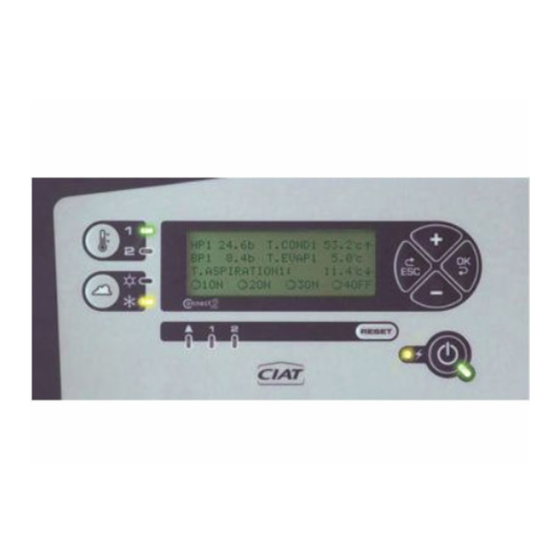
2.6 Description of the console (local and remote) Identification Visual Function On/off button LED state Meaning Machine stopped Machine operating Flashing Machine stopped by automatic operation control LED on = system powered on Fan fault acknowledgment *LED on = fault Press this button to select setpoint 1 or 2 The LEDs show the active setpoint. -
Page 7: Menu Tree
MENUS DESCRIPTION 1 - Setpoints Change setpoints - Menu not displayed if the unit is run with a CIAT water chiller. 2 - Machine state Default menu. Read only - information on the operation of the machine. 3 - Measured values Displays read-only temperature and pressure values. -
Page 8: Navigating Through The Menus
3 - NAVIGATING THROUGH THE MENUS Four buttons are available for navigating through the menus The use of each button is described in the table below: Press these buttons firmly! Button Menus level Parameters level Values level Back to Menus level Back to Parameters level Select menu Select parameter... -
Page 9: Board Functions: Description
4 - BOARD FUNCTIONS: DESCRIPTION 4.1 Control selection There are 4 types of control are possible depending on the value of parameter A07. ● On/Off: In-series control by activation of fan stages. ● Variable speed control: Fan speed control by EC motor. Mixed 1: Variable speed control on one stage then activation of the other On/Off stages depending on the speed of the EC fan ●... - Page 10 4.1.2 Speed control Used to control the speed of all fans with EC motors. ● The board sends a 0-10V signal to control the EC. ● The following diagram illustrates the output signal according to the measurement taken on the fluid (temperature or pressure) and the setpoint.
- Page 11 4.1.4 Mixed control 2 Used for variable speed control on stage 1. The other fan stages are controlled in series when the 1st stage is at 100%. The following diagram illustrates this operating mode for a system with 6 control stages. Hysteresis Stage 6 STAGE no.6 Hysteresis Stage 5...
-
Page 12: Machine Automatic Operation Control
● Control stage No. 1 (EC fan): The control signal (0 / 10V) of the stage # 1 varies as follows: A108 A107 - Measurement = A121 (or A122) – A106 → 0V Temp Temp - Measurement = A121 (or A122) + A106 → 10V outside outside Stage no 1... - Page 13 ● Optimised water consumption (A113 = WATER): The water misting does not start until all the stages are on and the measurement is above the value of parameter A200. With On/Off or Mixed control In this case, misting is controlled as an additional control stage. When the drycooler is at 100% power and the fluid temperature continues to increase to the value of parameter A200, misting is activated.
-
Page 14: Free-Cooling
See wiring diagram Terminal 5: Fluid towards the chiller Terminal 6: Fluid towards the drycooler Note: For CIAT water chillers, do not connect J3 1-2; instead, use the bus connection (J10 water chiller board/J9 drycooler board) EN7510364-00 EN - 12... -
Page 15: Warming Function
4.7.4 Operation e.g. Tu = 12°C A118 = 4 A117 = 2 Tu: Return operating temperature Ta = Free cooling off air temperature 12°C Ta = Tu – A117 FREE COOLING FREE COOLING Hysteresis When the outdoor temperature exceeds the value Ta, free operation operation Not zone... -
Page 16: Cms Link (Menu 11)
2 communication interfaces are possible (RS 485 and TCP) 4.10 Link with a CIAT chiller To establish communication between the water chiller and the drycooler, the following is required: 1) A BUS connection between the water chiller and the drycooler, using the following wiring: - Terminal block J10 of water chiller to J11 of the drycooler (for drycooler software versions <V09) -
Page 17: Options
Navigation in the drycooler board menus via the water chiller board. The drycooler configuration can be accessed from menu 13 of the water chiller board. All the drycooler board parameters are accessible in read and write mode. 1 3 - A E R O - C O N N E C T - Menu 13 displays all the drycooler data on the water chiller console. -
Page 18: Electrical Connections
6 - ELECTRICAL CONNECTIONS 6.1 Connection diagram 6.1.1 CMS link UNIT NO 1 Local board console 1 2 3 Controller or PC output RS485 B (-) UNIT J11 borne 3 A (+) J11 borne 1 NO. 2 J11 borne 2 RS485 2 wires Max length 1000m... -
Page 19: Board Connections
6.1.3 Link with a CIAT chiller DRYCOOLER board Local console 1 2 3 BOARD Water chiller B (-) A (+) Position of line termination resistance switch W3 OFF ON Position W3 if drycooler is the last unit in link Position W3 if drycooler is not the last unit in link 6.2 Board connections... - Page 20 CONNECTOR/TERMINALS DESIGNATION DIRECTION OF ACTION On/Off inputs J6 terminals 1-3 Fan manual override The fans turn on when the contact closes J6 terms. 2-3 Automatic operation control The machine stops when the contact opens J6 terminals 4-6 Setpoint 1/Setpoint 2 selection Setpoint 2 is enabled when the contact is closed.
- Page 21 ADD3 additional relay board (2 refrig. circuits) To be installed on the main board by the customer. Board delivered with a 30 cm connecting cable Its potential-free (dry) contacts allow the following information to be viewed remotely: CONNECTOR/TERMINALS DESIGNATION DIRECTION OF ACTION Relay board block J13 J9 terminals 1-2 Sensor fault, coil 2, circuit 2...
-
Page 22: Drycooler Configuration
7 - DRYCOOLER CONFIGURATION 7.1 Configurations Application: drycooler with one or two coils Flatbed unit Coil 2 Coil 2 Coil 1 Coil 1 (Forced draught) (Induced draught) V-type unit 7.2 System start-up and configuration ● Powering on the unit: The screen displays: "machine stopped on/off" in the [2-Machine status] menu Press ESC to go back to the menu list. - Page 23 Control = Mixed or speed control A114 From V12 A115 Mini speed threshold EC fan Mixed control 3 No longer visible from V09, see parameter Link with CIAT chiller A116 A316 Minimum T difference to deactivate free cooling Free cooling A117 From V03...
-
Page 24: Information Available While The Unit Is Running
7.3 Information available while the unit is running In the [2-Machine status] menu: menu displayed on the screen if the control console is not used for one hour. Default Information No faults Setpoint and measurement values displayed. Sensor fault The fault LED flashes and a message indicates that the sensor has a fault Fan fault The stage fault LED flashes and a message indicates which stage has a fault In the [3-Measured values] menu:... -
Page 25: Factory-Set Parameters
7.4 Factory-set parameters The [4 - Machine parameters] menu contains the parameters used to configure the machine. They are set in the factory and are appears at the top left of the screen. locked. The symbol Menu [4 - Machine parameters] In certain rare cases (such as adding the misting function), it may be necessary to update a parameter. -
Page 26: System Start-Up And Configuration
A114 Mini speed threshold EC fan Mixed control 3 From V12 A115 No longer visible from V09, see Link with CIAT master chiller A116 parameter A316 No. of setpoints per circuit or coil A120 Setpoint 1, circuit or coil 1... -
Page 27: Information Available While The Unit Is Running
8.3 Information available while the unit is running In the [2 - Machine status] menu: menu displayed on the screen if the control console is not used for one hour. Default Information No faults Setpoint and measurement values displayed. Sensor fault The fault LED flashes and a message states which loop has a fault Fan fault The fault LED flashes and a message states which stage has a fault... -
Page 28: Factory-Set Parameters
8.4 Factory-set parameters Menu [4-Machine parameters] The parameters of the [4-Machine parameters] menu contains the parameters used to configure the machine. They were set in the factory and are locked. The symbol appears at the top left of the screen. In certain rare cases (such as adding the misting function), it may be necessary to update a parameter. -
Page 29: Rs485 Transmission Mode (From V07)
9.2 RS485 transmission mode (From V07) 3-pin connector terminal block J11: terminal 1: A or + terminal 2: B or – terminal 3: for shielding The line termination resistance can be configured with jumper W3: Two LEDs assist in diagnosing communication: D50: incoming light. -
Page 30: Remote Alarm Register (Read-Only)
9.4 Remote alarm register (read-only) Register 10: FAN FAULTS (1 = active fault) Fan fault, stage 1, line 1 Fan fault, stage 1, line 2 Fan fault, stage 2, line 1 Fan fault, stage 2, line 2 Fan fault, stage 3, line 1 Fan fault, stage 3, line 2 Fan fault, stage 4, line 1 Fan fault, stage 4, line 2... -
Page 31: Counters (Read-Only)
9.7 Counters (read-only) Registers 300 and 301: Fan runtime, stage 1, line 1 Registers 302 and 303: Fan runtime, stage 2, line 1 Registers 304 and 305: Fan runtime, stage 3, line 1 Registers 306 and 307: Fan runtime, stage 4, line 1 Registers 308 and 309: Fan runtime, stage 5, line 1 Registers 310 and 311:... - Page 32 Registers 452 and 453: A121: Setpoint 1, coil 1, circuit 1 Registers 454 and 455: A122: Setpoint 2, coil 1, circuit 1 Registers 456 and 457: A123: Setpoint 1, coil 1, circuit 2 Registers 458 and 459: A124: Setpoint 2, coil 1, circuit 2 Registers 460 and 461: A125: Setpoint 1, coil 2, circuit 1 Registers 462 and 463:...
-
Page 33: Function 1, 2: Read N Bits
Registers 578 and 579: A113: Misting control voltage threshold Register 580: A129 Permanent fan fault 0 5 faults in 1 hour 1 After first fault Register 581: A109 Operation 0 Cooling 1 Warming without control 2 Warming with control Register 582 and 583: A109.1: Outdoor temperature warming operating order Register 584 and 585:... -
Page 34: Parameter Table
10 - PARAMETER TABLE TYPE OF MACHINE CONFIGURATION A01 Unit type FLATBED COILS V COIL A02 number of coils A03 Coil 1 type A04 Coil Circuit 1 A05 Coil 2 type A06 Coil Circuit 2 A07 Control type A08 Number of stages A09 Number of fan lines Figures Fig 1... - Page 35 MACHINE PARAMETERS Description Adjustment possible By default Display conditions Notes FLATBED COILS FLATBED UNIT TYPE V COIL COILS NUMBER OF COILS 1 or 2 If A01 = Flat YES (if 1 circuit) Parallel (on Vextra) = PARALLEL COILS If A01 = V NO (if 2 circuit) Same fluid as in the 2 coils 1 LT water circuit...
- Page 36 Description Adjustment possible By default Display conditions Notes TOP OF CIRCUIT.2 COIL.2 SENSOR RANGE 10 to 50 b (increments of 0.1) If A02 = 2 and A05 = 2 refrig. circuit BOTTOM OF CIRCUIT.2 COIL.2 SENSOR -1 to 10 bar (increments -0.5 If A02 = 2 and A05 = 2 refrig.
- Page 37 PARAMETER NAME PARAMETER ADJUSTMENT Notes Adjustment Adjustment Description Display conditions possible default conditions 1 setpoint A120 No. of SETPOINTS 2 per console or CMS SETPOINT 1 A02 = 1 and A03 = 1 5 to 90 A03 = 1 or 2 LT SETPOINT 1, COIL 1 A02 = 2 and A03 = 1 5 to 150...
- Page 38 PARAMETER NAME PARAMETER ADJUSTMENT Notes Adjustment Description Display conditions Adjustment possible default conditions STAGE 2 DIFFERENCE A02 = 1 and A03 = 1 and A08 ≥ 3 1 to 5°C If A03 = 1 or 2 (increments of 1) water circuits STAGE 3 COIL 1 DIFFERENCE A02 = 2 and A03 = 1 and A08 ≥...
- Page 39 PARAMETER NAME PARAMETER ADJUSTMENT Notes Adjustment Adjustment Description Display conditions By default possible conditions 1 to 20°C (in If A03 = 1 or 2 HYST. STAGE 1 CIRCUIT 2 A02 = 1 and A03 = 2 increments of 0.5) water circuits A161 2 to 6 bar (0.5 If A03 = 1 or 2...
- Page 40 PARAMETER NAME PARAMETER ADJUSTMENT Notes Adjustment Adjustment Description Display conditions By default possible conditions A02 = 2 and A05 = 1 and 1 to 10°C If A05 = 1 or 2 HYST. STAGE 4 COIL 2 A08 ≥ 4 (increments of 1) water circuit A178 A02 = 2 and A05 = 2 and...
-
Page 41: Glossary
PARAMETER NAME PARAMETER ADJUSTMENT Adjustment Description Display conditions Adjustment possible By default conditions MISTING PARAMETER IF P10 = YES and P113 = WATER A10 = YES A199 MISTING OUT. TEMPERATURE 20 to 40°C (in increments of 1) A113 = elec MISTING STAGE DIFFERENCE A02 = (1 or yes) and A03 = 1 If A03 = 1 or 2... - Page 42 CIAT Service www.ciat.fr This document is not legally binding. As part of our continuous drive to improve our products, CIAT reserves the right to make any technical modifications without prior notice. Registered address Avenue Jean Falconnier B.P. 14 01350 Culoz - France Tel.
Need help?
Do you have a question about the AeroCONNECT 1B and is the answer not in the manual?
Questions and answers