Advertisement
Quick Links
Advertisement

Subscribe to Our Youtube Channel
Related Manuals for Baxton Elsbeth LC22040705


Summary of Contents for Baxton Elsbeth LC22040705
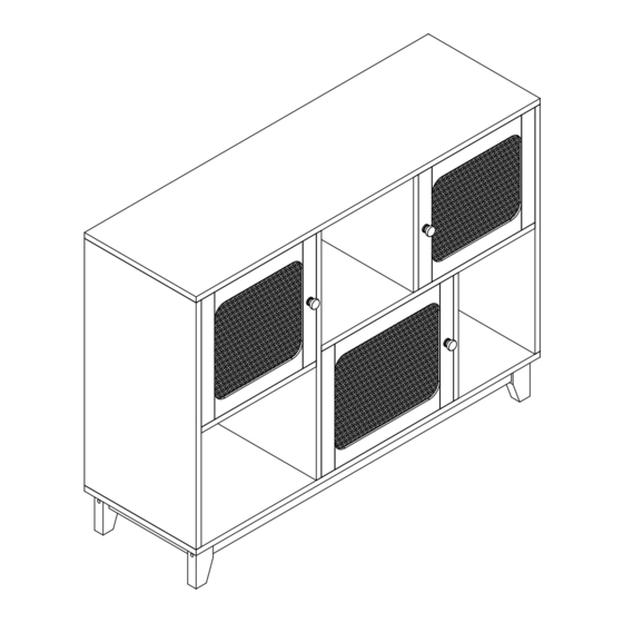
- Page 1 Sideboard ASSEMBLY INSTRUCTION Date last updated:07-29-2022...
-
Page 2: Hardware List
HARDWARE LIST 18 PCS 18 PCS 38 PCS 14 PCS 6 PCS 3 PCS 4 PCS 12 PCS Ø3.5x12mm 1 PCS 4 PCS 2 PCS 2 PCS 4 PCS 8 PCS 3 PCS 3 PCS 1 PCS 5 PCS 5 PCS 6 PCS... -
Page 3: Parts List
PARTS LIST 1- 1PCS 2- 1PCS 3- 1PCS 4- 1PCS 5- 1PCS 6- 1PCS 7- 1PCS 8- 1PCS 9- 1PCS 10- 1PCS 11- 1PCS 12- 1PCS 13- 2PCS 14- 2PCS 15- 2PCS 16- 2PCS... - Page 4 PARTS LIST 17- 1PCS 18- 1PCS 19- 1PCS 20- 1PCS...
-
Page 5: Assembly Steps
ASSEMBLY STEPS STEP 1. Fix magnetic door catch (O-1) to part 8 using screws (O-2), as shown. Insert quickfit screws (A) into part 8, as shown. A x2 O x1 STEP 2. Fix parts 6 and 7 to part 8 with woden dowels (C) and screws (D), as shown. C x4 D x4... - Page 6 ASSEMBLY STEPS STEP 3. Fix part 5 to part 6 using wooden dowels (C) and screws (D), as shown. C x2 D x2 STEP 4. Insert cam locks (B) and wooden dowels (C) into part 9, as shown. Fit part 9 to part 8. Turn cam locks clockwise to tighten.
- Page 7 ASSEMBLY STEPS STEP 5. Insert quickfit screws (A) into parts 2 and 3, as shown. A x4 STEP 6. Insert cam locks (B) and wooden dowels (C) into parts 5 and 8, as shown. Fit parts 2 and 3 to parts 5 and 8, as shown. Turn cam locks clockwise to tighten.
- Page 8 ASSEMBLY STEPS STEP 7. Fix part 17 to part 4 using screws (D), as shown. D x2 STEP 8. Insert wooden dowels (C) into parts 2, 6, 9 and 3 and attach to part 4 using screws (D), as shown. C x8 D x8...
- Page 9 ASSEMBLY STEPS STEP 9. Insert quickfit screws (A) into parts 13 and 15, as shown. A x4 STEP 10. G x4 I x1 Insert nuts (G-2) into parts 14, as shown. Fix parts 13 and 15 to parts 14 using bolts (G-1) and allen key (I), as shown.
- Page 10 ASSEMBLY STEPS STEP 11. Insert cam locks (B) into parts 16. Fit parts 13 and 15 to parts 16, as shown. B x4 Turn cam locks clockwise to tighten. STEP 12. Insert wooden dowels (C) into part 14 and 16, as shown. Attach screw covers (M) to the legs, as shown.
- Page 11 ASSEMBLY STEPS STEP 13. H x12 Fix assembled legs to part 4 using screws (H), as shown. STEP 14. Fix foot nails (J) to legs 13 and 15, as shown. Fix foot nails (Q) to leg 17 , as shown. Q x1 J x4...
- Page 12 ASSEMBLY STEPS STEP 15. Insert part 10 into grooves between parts 2 and 4, as shown. Insert part 12 into grooves between parts 3 and 4, as shown. STEP 16. Fix connecting braces (R) to connected parts 10 and 12 using screws (s), as shown. R x2 S x2...
- Page 13 ASSEMBLY STEPS STEP 17. Insert part 11 into groove of part 3, as shown. STEP 18. Fix connecting braces (R) to connected parts 11, 12 and 10 using screws (s), as shown. R x3 S x3...
- Page 14 ASSEMBLY STEPS STEP 19. A x8 Fix magnetic door catch (O-1) to part 1 using screws (O-2), as shown. Fit quickfit screws (A) into part 1, as shown. O x2 STEP 20. B x8 C x8 Insert cam locks (B) and wooden dowels (C) into parts 2, 6, 7 and 3, as shown. Fit part 1 to assembled unit, as shown.
- Page 15 ASSEMBLY STEPS STEP 21. K x2 N x8 Fix wall starps (K-1) on to parts 2 and 3 using screws (K-2), as shown. Fix corner brackets (N-2) to parts 10, 11 and 12 using screws (N-1), as shown. STEP 22. Fix handles (F-2) to doors 18, 19 and 20 using screws (F-1), as shown.
- Page 16 ASSEMBLY STEPS STEP 23. Press down breaing and fit doors 18, 19 and 20 into assembled unit, as shown. STEP 24. For extra stability, you must fix your sideboard to the wall using hardwares (L-1 and L-2), as shown. Screws (L-2) are fixed through wall straps and into the wall plugs (L-1). Should you choose not to affix the product to the wall, serious injury may be caused if the product tips over.
Need help?
Do you have a question about the Elsbeth LC22040705 and is the answer not in the manual?
Questions and answers