Table of Contents
Advertisement
Quick Links
™
TigerAccess
EE
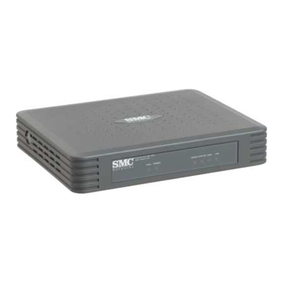
Ethernet-over-VDSL2 CPE
◆ High-speed Internet access over existing phone lines
◆ Concurrent data/phone services over single connection
◆ Always-on digital connection provides quick initialization
◆ Seamless rate adaptation enhances quality in video
applications
◆ Supports PC or Mac with Ethernet adapter card installed
Installation Guide
SMC7800A/VCP
Advertisement
Table of Contents

Related Manuals for SMC Networks SMC7800A


Summary of Contents for SMC Networks SMC7800A
-
Page 1: Installation Guide
◆ High-speed Internet access over existing phone lines ◆ Concurrent data/phone services over single connection ◆ Always-on digital connection provides quick initialization ◆ Seamless rate adaptation enhances quality in video applications ◆ Supports PC or Mac with Ethernet adapter card installed Installation Guide SMC7800A/VCP... - Page 3 TigerAccess-EE CPE Installation Guide From SMC’s Tiger line of feature-rich workgroup LAN solutions 20 Mason, Irvine, CA 92618 Phone: (949) 679-8000 February 2007 Pub. # 150200004100H...
- Page 4 Information furnished by SMC Networks, Inc. (SMC) is believed to be accurate and reliable. However, no responsibility is assumed by SMC for its use, nor for any infringements of patents or other rights of third parties which may result from its use. No license is granted by implication or otherwise under any patent or patent rights of SMC.
-
Page 5: Limited Warranty
All SMC products carry a standard 90-day limited warranty from the date of purchase from SMC or its Authorized Reseller. SMC may, at its own discretion, repair or replace any product not operating as warranted with a similar or functionally equivalent product, during the applicable warranty term. - Page 6 RIGHTS, WHICH MAY VARY FROM STATE TO STATE. NOTHING IN THIS WARRANTY SHALL BE TAKEN TO AFFECT YOUR STATUTORY RIGHTS. * SMC will provide warranty service for one year following discontinuance from the active SMC price list. Under the limited lifetime warranty, internal and external power supplies, fans, and cables are covered by a standard one-year warranty from date of purchase.
- Page 7 OMPLIANCES FCC - Class B This device complies with Part 15 of the FCC Rules. Operation is subject to the following two conditions: (1) This device may not cause harmful interference, and (2) this device must accept any interference received, including interference that may cause undesired operation. This equipment has been tested and found to comply with the limits for a Class B digital device, pursuant to Part 15 of the FCC Rules.
- Page 8 Classe B prescrites dans la norme sur le matérial brouilleur: “Appareils Numériques,” NMB-003 édictée par l’Industrie. CE Mark Declaration of Conformance for EMI and Safety (EEC) SMC contact for these products in Europe is: SMC Networks Europe, Edificio Conata II, Calle Fructuós Gelabert 6-8, 2 08970 - Sant Joan Despí, Barcelona, Spain.
- Page 9 RFI Emission: • Limit class A according to EN 55022:1998 • Limit class B for harmonic current emission according to EN 61000-3-2/1995 • Limitation of voltage fluctuation and flicker in low-voltage supply system according to EN 61000-3-3/1995 Immunity: • Product family standard according to EN 55024:1998 •...
- Page 10 OMPLIANCES Warnings and Cautionary Messages Warning: This product does not contain any serviceable user parts. Warning: Installation and removal of the unit must be carried out by qualified personnel only. Warning: When connecting this device to a power outlet, connect the field ground lead on the tri-pole power plug to a valid earth ground line to prevent electrical hazards.
- Page 11 OMPLIANCES Manufacturing Materials There are no hazardous nor ozone-depleting materials in this product. Documentation All printed documentation for this product uses biodegradable paper that originates from sustained and managed forests. The inks used in the printing process are non-toxic. Purpose This guide details the hardware features of the switches, including Its physical and performance-related characteristics, and how to install each switch.
- Page 12 OMPLIANCES viii...
-
Page 13: Table Of Contents
About the TigerAccess-EE CPE ....1-1 Overview ..........1-1 VDSL Technology . - Page 14 ABLE OF ONTENTS Glossary Index...
-
Page 15: About The Tigeraccess-Ee Cpe
HAPTER BOUT THE -EE CPE IGER CCESS Overview This Ethernet-Over-VDSL2 CPE system consists of an end-user CPE (Customer Premise Equipment) and a VDSL2 switch that are connected by standard telephone cable. The VDSL connection delivers an Ethernet data link rated up to 100 Mbps symmetric (full duplex), while simultaneously supporting standard telephone services. -
Page 16: About The Tiger Access -Ee Cpe
BOUT THE IGER CCESS MDF distribution equipment into the switch. The data and phone signals for each user are combined in the switch, and passed over VDSL lines to individual customers. The CPE at the customer end of the VDSL line connects to any PC or Macintosh equipped with a 10BASE-T or 100BASE-TX network interface card. -
Page 17: Vdsl Technology
VDSL Technology VDSL (Very High Bit-Rate Digital Subscriber Line) is at the high-end of all the DSL technologies, offering the best combination of fiber optics and copper to provide high-speed broadband Internet access. VDSL’s primary application is in providing a broadband data service to multi-tenant residential or commercial buildings. -
Page 18: Features And Benefits
BOUT THE IGER CCESS data rate in the downstream (receive) direction than in the upstream (transmit) direction. VDSL delivers high-performance online applications, such as high-quality video and other switched multimedia services. This Ethernet VDSL2 CPE system provides robust performance, with a symmetric data rate up to 100 Mbps, and a range up to 200 meters (656 ft). -
Page 19: System Requirements
• Supports ITU-T VDSL/VDSL2 and ANSI T1E1.4 Part 1 VDSL interface standards, as well as other evolving ETSI, ANSI, and ITU VDSL standards for the copper local loop • Spectral compatibility with VDSL, VDSL2, ADSL, ADSL2+, ISDN (2B1Q/4B3T), Smartphone digital PBX extensions and narrowband interference •... - Page 20 BOUT THE IGER CCESS • Power requirements: 12 VDC via the included AC power adapter. Make sure that a properly grounded power outlet is within 1.8 m (6 ft) of the CPE. • The CPE should be located in a cool dry place, with at least 5 cm (2 in.) of space on all sides for ventilation.
-
Page 21: Hardware Description
ARDWARE Unpacking After unpacking this CPE, check the contents to be that sure you have received all the components. Then, before beginning the installation, be sure that you have all other necessary installation equipment. Please inform your dealer if there are any incorrect, missing, or damaged parts. -
Page 22: Front And Rear Panel
The following figure shows the external components of the CPE: System Indicators VDSL Port Phone Port Ethernet Status TigerAccess EE CPE SMC7800A VCP DIAG POWER DIP Switches Ethernet Port Figure 2-1 Front and Rear Panels Port Link/Activity... -
Page 23: System And Port Status Leds
System and Port Status LEDs The CPE includes key system and port indications that simplify installation and network troubleshooting. The LEDs, which are located on the front panel for easy viewing, are described in the following table. System Status Indicators POWER DIAG Port Status Indicators... - Page 24 ARDWARE ESCRIPTION...
-
Page 25: Installation
Installation Overview Before installing the CPE, verify that you have all the items listed in the “Unpacking” on page 2-1. If any of the items are missing or damaged, contact your local distributor. Also, be sure you have all the necessary tools and cabling before installing the CPE. -
Page 26: Powering On
NSTALLATION 1. Using standard telephone cable, connect the CPE’s RJ-11 LINE port to the RJ-11 telephone wall jack providing the VDSL service. 2. Connect a telephone or fax machine to the RJ-11 port on the CPE labeled PHONE. 3. For the Ethernet connection, make sure you have installed a 10BASE-T or 100BASE-TX network adapter card in the computer. -
Page 27: Configuring The Tcp/Ip Protocols
TCP/IP P ONFIGURING THE ROTOCOLS Configuring the TCP/IP Protocols To connect the CPE to a computer through its Ethernet port, the computer must have an Ethernet network adapter card installed, and be configured for the TCP/IP protocol. Many service providers configure TCP/IP for client computers automatically using a networking technology known as Dynamic Host Configuration Protocol (DHCP). - Page 28 NSTALLATION Windows XP 1. Click “Start/Control Panel/Network Connections.” 2. Right-click the “Local Area Connection” icon for the adapter you want to configure. 3. Highlight “Internet Protocol (TCP/IP).” 4. Click on “Properties.” 5. Select the option “Obtain an IP address automatically” and “Obtain DNS server address automatically.”...
-
Page 29: Diagnosing Cpe Indicators
Diagnosing CPE Indicators CPE operation is easily monitored via the LED indicators to identify problems. The table below describes common problems you may encounter and possible solutions. If the solutions in the table fail to resolve the problem, contact technical support for advice. Symptom POWER indicator does not... -
Page 30: Troubleshooting
ROUBLESHOOTING Table A-1 Troubleshooting Chart (Continued) VDSL indicator does not light up after making a connection. If You Cannot Connect to the Internet • Check that your computer is properly configured for TCP/IP. See “Configuring the TCP/IP Protocols” on page 3-3. •... -
Page 31: Cables
Twisted-Pair Cable and Pin Assignments For 10BASE-T and 100BASE-TX connections, the twisted-pair cable must have two pairs of wires. Each wire pair is identified by two different colors. For example, one wire might be green and the other, green with white stripes. -
Page 32: 10Base-T/100Base-Tx Pin Assignments
ABLES 10BASE-T/100BASE-TX Pin Assignments Use unshielded twisted-pair (UTP) or shielded twisted-pair (STP) cable for RJ-45 connections: 100-ohm Category 3, 4 or 5 cable for 10 Mbps connections, or 100-ohm Category 5 cable for 100 Mbps connections. Also be sure that the length of any twisted-pair connection does not exceed 100 meters (328 feet). -
Page 33: Straight-Through Wiring
Straight-Through Wiring If twisted-pair cable is to join two ports and only one of the ports has an internal crossover (MDI-X), the two pairs of wires must be straight-through. (When auto-negotiation is enabled for the RJ-45 port on the CPE, you can use either straight-through or crossover cable to connect to any device type.) 10/100BASE-TX Straight-through Cable End A... -
Page 34: Crossover Wiring
ABLES Crossover Wiring If the twisted-pair cable is to join two ports and either both ports are labeled with an “X” (MDI-X) or neither port is labeled with an “X” (MDI), a crossover must be implemented in the wiring. (When auto-negotiation is enabled for the RJ-45 port on the CPE, you can use either straight-through or crossover cable to connect to any device type.) End A... -
Page 35: Rj-11 Ports
RJ-11 P ORTS RJ-11 Ports Standard telephone RJ-11 connectors and cabling can be found in several common wiring patterns. These six-pin connectors can accommodate up to three wire-pairs (three telephone lines), but usually only one or two pairs of conductor pins and wires are implemented. The RJ-11 ports on the side of the CPE contain two wire-pairs, an inner pair (pins 3 and 4) and outer pair (pins 2 and 5). - Page 36 ABLES Table B-2 RJ-11 Port Pinouts Signal Name Wire Color Not used Line 2 Tip Black or White/Orange Line 1 Ring Red or Blue/White Line 1 Tip Green or White/Blue Line 2 Ring Yellow or Orange/White Not used...
-
Page 37: Specifications
VDSL Functional Criteria Band Plan: Up to 6 bands Signal Bandwidth: 25 kHz to 30MHz Optional Band: US0 operating at 4~25 kHz (low end) to 138~276 kHz (high end) Multi-Carrier-Modulation (MCM) - DMT modulation Interleaving: general convolution Tone Spacing: 8.6 kHz Upstream Power Back-off (UPBO) Remote firmware upgrade Physical Characteristics... -
Page 38: Standards
PECIFICATIONS Power Consumption 7 Watts maximum Input Power 12 VDC (via AC power adapter), 1 A maximum Typical 700 mA maximum Size 15.5 x 12.85 x 2.8 cm (6.1 x 5.06 x 1.1 in.) Weight 374 g (13.19 oz) Temperature Operating: 0 °C to 40 °C (32 °F to 104 °F) Storage: -40 °C to 70 °C (-40 °F to 158 °F) Humidity... -
Page 39: Compliances
OMPLIANCES Compliances CE Mark Emissions FCC Class B FCC Part 68 Industry Canada Class B EN55022 (CISPR 22) Class B EN 61000-3-2/3 CNS 13438 Class B Immunity EN 61000-4-2/3/4/5/6/8/11 Safety CSA/CUS (CSA 22.2. NO 60950-1 & UL60950-1) CB (IEC60950-1) - Page 40 PECIFICATIONS...
- Page 41 10BASE-T IEEE 802.3 specification for 10 Mbps Ethernet over two pairs of Category 3, 4, or 5 UTP cable. 100BASE-TX IEEE 802.3u specification for 100 Mbps Fast Ethernet over two pairs of Category 5 or better UTP cable. Auto-Negotiation Signalling method allowing each node to select its optimum operational mode (e.g., speed and duplex mode) based on the capabilities of the node to which it is connected.
- Page 42 LOSSARY Ethernet A network communication system developed and standardized by DEC, Intel, and Xerox, using baseband transmission, CSMA/CD access, logical bus topology, and coaxial cable. The successor IEEE 802.3 standard provides for integration into the OSI model and extends the physical layer and media with repeaters and implementations that operate on fiber, thin coax and twisted-pair cable.
- Page 43 Local Area Network (LAN) A group of interconnected computer and support devices. Media Access Control (MAC) A portion of the networking protocol that governs access to the transmission medium, facilitating the exchange of data between network nodes. Management Information Base (MIB) An acronym for Management Information Base.
- Page 44 LOSSARY Transmission Control Protocol/Internet Protocol (TCP/IP) Protocol suite that includes TCP as the primary transport protocol, and IP as the network layer protocol. Unshielded twisted-pair cable. User Datagram Protocol (UDP) provides a datagram mode for packet-switched communications. It uses IP as the underlying transport mechanism to provide access to IP-like services.
- Page 45 Numerics 10BASE-T/100BASE-TX pin assignments B-2 cable crossover B-4 straight-through B-3 testing category 5 cable B-4 cable connections 3-1 compliances emissions C-3 immunity C-3 safety C-3 description 1-1 features 1-4 crossover Ethernet cable B-4 front panel 2-2 hardware, description 2-2 installation connecting cables 3-1 powering on 3-2 LED indicators, problems A-1...
- Page 46 NDEX Index-2...
- Page 48 North West Africa: CIS: PRC: Taiwan: Asia Pacific: Korea: Japan: Australia: India: If you are looking for further contact information, please visit www.smc.com, www.smc-europe.com, or www.smc-asia.com. 20 Mason Irvine, CA 92618 Phone: (949) 679-8000 (800) SMC-4-YOU; Fax (949) 679-1481 34-91-352-00-40; Fax 34-93-477-3774 44 (0) 1932 866553;...
Need help?
Do you have a question about the SMC7800A and is the answer not in the manual?
Questions and answers