
Related Manuals for GFA ELEKTROMAT SE 10.100 FU-25,40


Summary of Contents for GFA ELEKTROMAT SE 10.100 FU-25,40
- Page 1 Installation Instructions ELEKTROMAT SE 10.100 FU-25,40 RP10V/100GDU Model: 10003977 10005 -en- Status: 16.11.2022...
- Page 2 GfA ELEKTROMATEN UK Ltd Titan Business Centre Spartan Close Warwick CV34 6RR United Kingdom sales@gfa-elektromaten.co.uk www.gfa-elektromaten.co.uk...
-
Page 3: Table Of Contents
Table of contents General safety information ....................4 Technical data ........................ 6 Special version with vent screw ..................8 Mechanical installation ....................9 Electrical installation ..................... 13 Limit switch adjustment ....................14 ... -
Page 4: General Safety Information
The safe operation of the product can only be ensured if it is used as specified. Follow the installation instructions. Observe all specifications, especially warnings, when installing the product in the overall system. GfA is not liable for damage resulting from non-observance of the installation instructions. The resulting overall system must be reassessed for its safety in accordance with applicable standards and directives (e.g. - Page 5 Warning - Failure to follow these installation instructions may result in severe injury or death. Please read these instructions before using the product. Keep these instructions handy. Include these instructions when passing on the product to third parties. Warning - Danger from improper use of the product! ...
-
Page 6: Technical Data
2 Technical data Designation Unit Output speed Output torque 100 (65) Output / hollow shaft 25,40 Series SG 63 Limit switch range (maximum revolutions of the output / hollow shaft) Supply voltage 1N~ 230 / 3~ 230 Operating current 6,60 Operating frequency 50/60 Power factor cos φ... - Page 7 1) Specification in ( ) according to EN 60335-2-103. 2) When using a temperature range of +40°...+60°C use half of maximum cycles per hour.
-
Page 8: Special Version With Vent Screw
3 Special version with vent screw This drive unit is equipped with a vent screw. The escape of small amounts of oil in the vent screw is not problematic. Position SG50 SG63 SG85 SG115 BAFV0 0 1 0 0 1 BAFV0 0 2 0 0 1 BAFV0 0 3 0 0 1 BAFV0 0 4 0 0 1... -
Page 9: Mechanical Installation
4 Mechanical installation Prerequisites The permissible loads on walls, fastenings, mountings and transmission elements must not be exceeded, even for maximum holding torques or locking torques (▶ refer to technical data). Connection elements ▶ Self-locking connection ▶ Utilize the hole diameter ▶... - Page 10 Mounting Eight threads are provided for mounting (①). A key is used to connect to the door shaft. ▶ Use a key that is at least as long as the hollow shaft (②). BAGAD0 2 0 0 3 _Z0 0 2...
- Page 11 Installation The descriptions below apply to general door specifications. The specifications of the door manufacturer must also be observed during installation. Warning - Potential injury or danger to life! During installation, be sure to use a lifting device that has a sufficient load- carrying capacity.
- Page 12 ▶ Attach the drive unit. BAGAE0 2 0 0 5 _Z0 0 2 ▶ Tighten all connection elements (M8) to 25 BAGAE0 2 0 0 9 _Z0 0 2 Nm. Install all other connection elements according to the specifications of the door manufacturer.
-
Page 13: Electrical Installation
5 Electrical installation Warning - Danger to life from electric current! Switch the mains OFF and check that the cables are de-energised Observe the applicable regulations and standards Make a proper electrical connection Use suitable tools Performing electrical installation Remove the cover. -
Page 14: Limit Switch Adjustment
6 Limit switch adjustment The adjustment of the final limit positions OPEN and CLOSE is described in the instructions for the door control panel. The door control must meet Performance Level c! Use only door controls that evaluate the limit switch according to EN 12453 and meet Performance Level c. -
Page 15: Motor Connection
7 Motor connection Motor X13 Motor plug Spring applied brake 8 Limit switch connection S10 Emergency manual operation X12 DES connection Safety circuit Channel B (RS485) Ground Channel A (RS485) Safety circuit Supply voltage Connection cable freqency inverter (FI) -
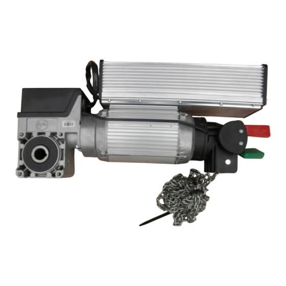
Page 16: Emergency Manual Operation (Hand Chain Operator)
9 Emergency manual operation (hand chain operator) Emergency manual operation is designed for opening or closing the door without power supply. Its activation interrupts the control voltage. Electrical operation is no longer possible. Warning – Injuries due to incorrect operation! ... - Page 17 Switch on by pulling the red handle. Open or close by pulling the chain. Switch off by pulling the green handle.
-
Page 18: Completing Commissioning / Inspection
10 Completing commissioning / inspection Check the following components and then install all covers. Gearbox Check the drive unit for loss of oil (a few drops can be neglected). Protect the output-shaft permanently against corrosion. Mounting Check that all connection elements (consoles, torque mounts, screws, locking rings, etc.) are secure and in proper condition. - Page 19 Brake Warning - Potential injury or danger to life! Carry out a brake test. Overrun depends on the door and its equipment. The specifications of the door manufacturer must be observed. Brake lift may only be used in the final limit position CLOSE for doors that have no counter-balancing.
-
Page 20: Disposal
Dispose of old devices properly according to local legal regulations. Return old devices to the return and collection systems available. You can also return GfA products free of charge. Please apply enough postage to the package and mark it as "old devices". -
Page 21: Declaration Of Incorporation / Declaration Of Conformity
EMC Directive 2014/30/EU within the meaning of RoHS Directive 2011/65/EU The following requirements from Appendix I of GfA ELEKTROMATEN GmbH & Co. KG the Machinery Directive 2006/42/EC are met: declare under our sole responsibility that the 1.1.2, 1.1.3, 1.1.5, 1.2.2, 1.2.3, 1.2.6, 1.3.2,... -
Page 22: Ukca: Declaration Of Incorporation / Declaration Of Conformity
Restriction of the Use of Certain Hazardous Substances in Electrical and Electronic Equipment Regulations 2012 The following requirements from Appendix I of GfA ELEKTROMATEN GmbH & Co. KG the Supply Machinery (Safety) Regulations 2008 declare under our sole responsibility that the...
Need help?
Do you have a question about the ELEKTROMAT SE 10.100 FU-25,40 and is the answer not in the manual?
Questions and answers