GFA ELEKTROMAT SE 14.80 FU-25,40 ER Installation Instructions Manual
Hide thumbs
Also See for ELEKTROMAT SE 14.80 FU-25,40 ER:
- Installation instructions manual (20 pages)

Related Manuals for GFA ELEKTROMAT SE 14.80 FU-25,40 ER


Summary of Contents for GFA ELEKTROMAT SE 14.80 FU-25,40 ER
- Page 1 Installation Instructions ELEKTROMAT SE 14.80 FU-25,40 ER Model: 10004013 10011 -en- Status: 02.07.2023...
- Page 2 GfA ELEKTROMATEN GmbH & Co. KG Wiesenstraße 81 D-40549 Düsseldorf www.gfa-elektromaten.de info@gfa-elektromaten.de...
-
Page 3: Table Of Contents
Table of contents General safety information ....................4 Technical data ........................ 6 Mechanical installation ....................7 Electrical installation ..................... 12 Limit switch adjustment ....................13 Motor connection ......................14 ... -
Page 4: General Safety Information
The safe operation of the product can only be ensured if it is used as specified. Follow the installation instructions. Observe all specifications, especially warnings, when installing the product in the overall system. GfA is not liable for damage resulting from non-observance of the installation instructions. The resulting overall system must be reassessed for its safety in accordance with applicable standards and directives (e.g. - Page 5 Warning - Failure to follow these installation instructions may result in severe injury or death. Please read these instructions before using the product. Keep these instructions handy. Include these instructions when passing on the product to third parties. Warning - Danger from improper use of the product! ...
-
Page 6: Technical Data
2 Technical data Designation Unit Output speed Output torque 140 (140) Output / hollow shaft 25,40 Series SG 50E Limit switch range (maximum revolutions of the output / hollow shaft) Supply voltage 1N~ 230 / 3~ 230 Operating current 6,60 Operating frequency 50/60 Power factor cos φ... -
Page 7: Mechanical Installation
3 Mechanical installation Prerequisites The permissible loads on walls, fastenings, mountings and transmission elements must not be exceeded, even for maximum holding torques or locking torques (▶ refer to technical data). Connection elements: Self-locking connection Utilize the hole diameter to Use adequately elements with a minimum the full. - Page 8 Mounting Eight threads are provided for mounting. Use at least 2 of these (①). Keys are used to connect to the door shaft. Use a key that is at least as long as the hollow shaft (②). BAGAD0 1 0 0 1 _Z0 0 2 8 x (M8x16)
- Page 9 Installation The descriptions below apply to general door specifications. The specifications of the door manufacturer must also be observed during installation. Warning - Potential injury or danger to life! During installation, be sure to use a lifting device that has a sufficient load- carrying capacity.
- Page 10 Attach the drive unit. BAGAE0 1 0 0 3 _Z0 0 3 Note – possible stalling of the gearbox! Do not hit the gearbox with a hammer when placing the drive unit on the shaft. Hammer blows or similar impacts of force may stall the gearbox. Tighten all connection elements (M8) to 25 BAGAE0 1 0 0 6 _Z0 0 2 Nm.
- Page 11 Secure the keys (version Ⓑ only). BAGAE0 1 0 0 7 _Z0 0 2...
-
Page 12: Electrical Installation
4 Electrical installation Warning - Danger to life from electric current! Switch the mains OFF and check that the cables are de-energised Observe the applicable regulations and standards Make a proper electrical connection Use suitable tools Performing electrical installation Remove the cover. -
Page 13: Limit Switch Adjustment
5 Limit switch adjustment The adjustment of the final limit positions OPEN and CLOSE is described in the instructions for the door control panel. The door control must meet Performance Level c! Use only door controls that evaluate the limit switch according to EN 12453 and meet Performance Level c. -
Page 14: Motor Connection
6 Motor connection Motor X13 Motor plug 7 Limit switch connection X12 DES connection BANA101104_Z001 Safety circuit Channel B (RS485) Ground Channel A (RS485) RS 485 Safety circuit Supply voltage Connection cable freqency inverter (FI) -
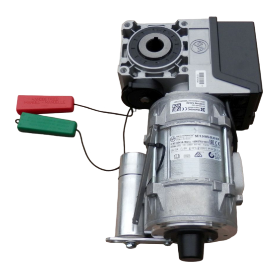
Page 15: Emergency Manual Operation (Release)
8 Emergency manual operation (release) Emergency manual operation is designed for opening or closing the door without power supply. Warning – Injuries due to incorrect operation! Switch off voltage. Door movement possible after release Warning - Danger of the door dropping! If you need to apply more than the permissible force of 390N (according to DIN EN 12604/DIN EN 12453) to move the door by emergency manual operation, this indicates a stalling on the drive unit or door. - Page 16 Switch on by pulling the red handle. Open or close the door by hand. Switch off by pulling the green handle.
-
Page 17: Completing Commissioning / Inspection
9 Completing commissioning / inspection Check the following components and then install all covers. Gearbox Check the drive unit for loss of oil (a few drops can be neglected). Protect the output-shaft permanently against corrosion. Mounting Check that all connection elements (consoles, torque mounts, screws, locking rings, etc.) are secure and in proper condition. -
Page 18: Disposal
Dispose of old devices properly according to local legal regulations. Return old devices to the return and collection systems available. You can also return GfA products free of charge. Please apply enough postage to the package and mark it as "old devices". -
Page 19: Declaration Of Incorporation / Declaration Of Conformity
EMC Directive 2014/30/EU within the meaning of RoHS Directive 2011/65/EU The following requirements from Appendix I of GfA ELEKTROMATEN GmbH & Co. KG the Machinery Directive 2006/42/EC are met: declare under our sole responsibility that the 1.1.2, 1.1.3, 1.1.5, 1.2.2, 1.2.3, 1.2.6, 1.3.2,... -
Page 20: Ukca: Declaration Of Incorporation / Declaration Of Conformity
Restriction of the Use of Certain Hazardous Substances in Electrical and Electronic Equipment Regulations 2012 The following requirements from Appendix I of GfA ELEKTROMATEN GmbH & Co. KG the Supply Machinery (Safety) Regulations 2008 declare under our sole responsibility that the...
Need help?
Do you have a question about the ELEKTROMAT SE 14.80 FU-25,40 ER and is the answer not in the manual?
Questions and answers