Table of Contents
Advertisement
Quick Links
Service Manual_2023-V1.0
Service Manual
Wine Cooler SERIES
Applicable Models
Model Code
Applicable Models
HS-129WE(N)
UR-JC99GE-DQ
22033010001682
The picture in this service manual is only for reference, and specific
appearance and configuration are subject to the real product.
This manual mainly teaches the method, the specific work skill needs
engineer to accumulate through the daily work.
1
Advertisement
Table of Contents

Subscribe to Our Youtube Channel
Related Manuals for Midea HS-129WE(N)


Summary of Contents for Midea HS-129WE(N)
- Page 1 Service Manual_2023-V1.0 Service Manual Wine Cooler SERIES Applicable Models Model Code Applicable Models HS-129WE(N) UR-JC99GE-DQ 22033010001682 The picture in this service manual is only for reference, and specific appearance and configuration are subject to the real product. This manual mainly teaches the method, the specific work skill needs engineer to accumulate through the daily work.
- Page 2 Manufacturers or distributors are not responsible for the content of the Manual and interpretation thereof. Midea Refrigerators Technical Maintenance Manual Copyright @2017 All rights reserved. Replication of all or part of the Manual in any forms shall not be allowed without written approval by the Overseas Sales Corporation of Midea Refrigerators.
-
Page 3: Table Of Contents
Service Manual_2023-V1.0 Contents SIGNIFICANT UPDATE NOTES (NONE) ......................5 2. SAFETY WARNING CODE ............................6 2.1 W ARNING FOR OPERATION SAFETY ........................... 6 2.2 S ......................... 8 AFETY INSTRUCTION FOR REFRIGERANT 3. TRANSPORT ................................9 3.1 H ANDLING ................................... 9 4. INSTALLATION AND COMMISSIONING ......................10 4.1 D ISASSEMBLY AND SSEMBLY... - Page 4 Service Manual_2023-V1.0 9.5 D EFROST FUNCTION ..............................29 9.6 B ACKUP DATA FOR POWER FAIL ..........................29 10. COMPRESSOR ..............................31 10.1 C OMPRESSOR ON AND OFF ONTROL SPECIFICATIONS ..................31 11. TROUBLESHOOTING METHOD ........................32 11.1 N ) ......................32 O COOLING IR COOLING LECTRONIC...
-
Page 5: Significant Update Notes (None)
Service Manual_2023-V1.0 1. Significant update notes (None) -
Page 6: Safety Warning Code
Service Manual_2023-V1.0 2. Safety Warning Code 2.1 Warning for operation safety Important Safety Instructions CAUTION RISK OF ELECTRIC SHOCK DO NOT OPEN This symbol indicates that dangerous voltage constituting a risk of electric shock is present within your freezer. This symbol indicates that there are important operating and maintenance instructions in the literature accompanying your freezer. - Page 7 Service Manual_2023-V1.0 CONNECTING ELECTRICITY Electrical Shock Hazard. Failure to follow these instructions can result in death, fire, or electrical shock. Plug into a grounded 3-prong outlet. Do not remove the ground prong. Do not use an adapter. WARNING Electric Shock Hazard Failure to follow these instructions can result in electric shock, fire, or death.
-
Page 8: Safety Instruction For Refrigerant
Service Manual_2023-V1.0 responsibility to comply with federal and local regulations when disposing of this product. 12) This freezer is intended to be used in household and similar environments. 13) Do not store or use gasoline or any flammable liquids inside or in the vicinity of this freezer. -
Page 9: Transport
Service Manual_2023-V1.0 3. Transport 3.1 Handling Handling 1)Protect the refrigerator in moving it,Same as shown as lef t photo, please move it by handcart with cushion 2)Remove all packing materials and bottom cushion, the m ove into house for placement 3)After moving it to appropriate location, wait for 2 hours bef ore power on. -
Page 10: Installation And Commissioning
Service Manual_2023-V1.0 4. Installation and commissioning 4.1 Door Disassembly and Assembly The refrigerator door needs to be dismantled if it cannot enter the room in the whole. 4.2 Installation location Installation location Location that is easy for ventilation shall be chosen to facilitate heat dissipation, enhance its performance and reduce the energy consumption. -
Page 11: Left Or Right Open Door Reversal
Service Manual_2023-V1.0 4.4 Left or right open door reversal 1)Change the installation location of the upper hinge⑤ of the beverage cabinet, then the opening direction of the door could be changed at will. Please follow the following instructions for the change of the opening direction of the beverage cabinet's door (for instance: from right-handed door to left-handed door): close the glass door of the beverage cabinet, use a blade to... -
Page 12: Installation Of Handle(None
Service Manual_2023-V1.0 5)Put the aforesaid glass door on the lower hinge, and fix the upper hinge⑤. Align the door with the cabinet and check the tightness of gasket, and then install all the ornaments②③. 4.5 Installation of handle(None) 4.6 Installation of door lock(None)... -
Page 13: Product Configuration And Dimension
Service Manual_2023-V1.0 5. Product configuration and dimension 5.1 Main parts and their names (The picture is only for reference, and specific appearance and configuration are subject to the real product) -
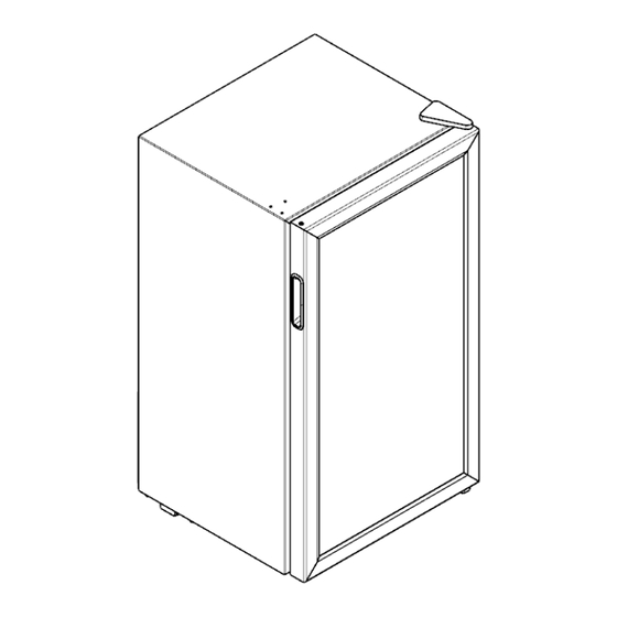
Page 14: External Dimension
Service Manual_2023-V1.0 5.2 External dimension HS-125WN Code Description Size (mm) Height to Top of Case Width Depth w/Cabinet Depth w/Door Depth (Door open 90 deg. w) Depth (Door open 135 deg. w) Width (Door open 135 deg. w) (The picture is only for reference) -
Page 15: Location Of S/N
Service Manual_2023-V1.0 5.3 Location of S/N Some products also have S/N on the lower part of the right side of the Cabinet. -
Page 16: Product Specification
Service Manual_2023-V1.0 6. Product specification 6.1 Electrical parameters UR-JC99GE- DQ Product Name Applicable Models HS-129WE(N) Item Specification Refrigerant R600a FZ35S1L-U Compressor QPS2-B4R7MG1 Starter(PTC) Overload protector(OLP) DRB18T61A1 None Integrate PTC+OLP Capacitor None None Power filter Rmc:14.8Ω±7% Winding resistance of compressor wiring terminal Rsc: 8.4Ω±7% (20℃) Rms=Rmc+Rsc... -
Page 17: Circuit Diagram
Service Manual_2023-V1.0 6.3 Circuit diagram... -
Page 18: Refrigerating Piping System And Circulating Route Of Cooling Air
Service Manual_2023-V1.0 7. Refrigerating piping system and circulating route of cooling air 7.1 Refrigerating piping system ❶Compressor→❷Whole condenser→❸Dry filter tube→❹Capillary tube→❺Evaporator→❻Suction tube→❶Compressor... -
Page 19: Dismantling Of Parts
Service Manual_2023-V1.0 8. Dismantling of parts 8.1 Parts on the door Door seal Door seal is installed into door liner groove. 1) Open the wine cabinet door; 2) Take the door seal ①out of door liner. 8.2 Parts inside the refrigerator wine rack 1)Lift up the division plate with a proper force and pull it out towards yourself;... -
Page 20: Light System
Service Manual_2023-V1.0 8.3 Light system Light Light of the refrigerating chamber is located chamber. 1)Remove two fixed screws from the main control board in refrigerator. 2)Pull out the mounting box horizontally and unplug the wiring terminal on the LED lamp; 3)Invert the main control panel mounting box;... -
Page 21: Evaporator And Temperature Sensing System
Service Manual_2023-V1.0 8.4 Evaporator and temperature sensing system Evaporator in refrigerating chamber Evaporator in refrigerating chamber 1)Take down screws and gaskets on the evaporator.. 2)Remove the welding on inlet and outlet tubes. 8.5 Compressor case Rear cover None Compressor and the cooling system pipe 1)Cut off the power, remove the goods in the refrigerator, with the tape to make the door fixed firmly and prevent the door dropping when the refrigerator... - Page 22 Service Manual_2023-V1.0 3)Cut off the compressor pipeline.-❶Cut off the process pipeline.-❷Cut off the low-pressure muffler.- ❸Cut off the high-pressure exhaust pipe. 4-1)Remove the screws(for some models) -Two screws outside -One screw inside 4-2)Remove the metal clamp(for some models) -Disassembly the metal clamp that is fix the electric appliance shield 5)Remove the clipping strip Slowly pull it out...
- Page 23 Service Manual_2023-V1.0 7)Remove the starter and protector Unplug the starter and protector (you can use a screwdriver to pry it slowly) 8)Loosen the screw of the compressor bottom plate, remove the floor together with the compressor from the box. 9)Use the wrench to remove the bolts by steps❹❺❻❼, replace the compressor and reverse process can complete installation.
- Page 24 Service Manual_2023-V1.0 11)Replace the compressor and welding the compressor pipeline.-❿Welding the process pipeline.- ⓫Welding the low-pressure muffler.-⓬Welding the high-pressure exhaust pipe. 12)Replace the filter, Cu-Fe tubes welding ⓭ used Ag welding rod, Cu-Cu tubes welding ⓮ used Cu welding rod. 13)Vacuum system,The degree of vacuum below 6Pa.
- Page 25 Service Manual_2023-V1.0 Piping system in the compressor case ❶ Condenser-1(out) ❷Drier ❸Capillary Tube ❹Sution Tube ❺Compressor cover ❻Compressor ❼ Condenser-1(in) ❽drain tray ❾Main control board mounting box Drain tray 1)Pull out the drain tray 2)Replace the drain tray, the reverse process can complete installation.
-
Page 26: Display Control Board
Service Manual_2023-V1.0 8.6 Display control board Display control board Take down the two screws on the box Take down the box Take down the display control board... -
Page 27: Main Control Board
Service Manual_2023-V1.0 8.7 Main control board Main control board Take down screws Take out main control panel cover Disconnect the fast connector Take screws on main control panel... -
Page 28: Function And Operation
Service Manual_2023-V1.0 9. Function and operation 9.1 Operation panel 9.2 Temperature control UI Control ●Powering on each time, the display screen gives a full display for 3s and meanwhile the start-up sound rings; then the machine enters into operation in the locked state ●The corresponding fault code will be displayed when a fault occurs;... -
Page 29: Open Door Alarm (None)
Service Manual_2023-V1.0 Temperature setting ●Press the Temperature-rise key , the temperature will increase 1℃ (or 1℉). After locking, the cooler will operate according to the setting temperature; , the temperature will decrease 1℃ (or ℉). After ●Press the Temperature-drop key locking, the cooler will operate according to the setting temperature ●The wine cooler‘s temperature can be set between 7~18℃(44~65℉)... - Page 30 Service Manual_2023-V1.0 continuously. The running state of the refrigerator is remembered after change function settings and lock. When the refrigerator is out of power and recharged, the running state of the refrigerator is same as before .
-
Page 31: Compressor
Service Manual_2023-V1.0 10. Compressor 10.1 Compressor on and off Control specifications 1.1 When one of the following conditions is met, the compressor stops: 1) Tr ≤ Trt; 2) The compressor runs continuously for more than 3 hours (Stop 5 minutes); 1.2 When all the following conditions are met, the compressor starts up: 1) Tr ≥Trk;... -
Page 32: Troubleshooting Method
Service Manual_2023-V1.0 11. Troubleshooting Method 11.1 No cooling (Air cooling-Electronic) - Page 33 Service Manual_2023-V1.0...
-
Page 34: No Working Of Compressor
Service Manual_2023-V1.0 11.2 No working of compressor... -
Page 35: Inside Frosting, No Defrosting
Service Manual_2023-V1.0 11.3 Inside frosting, no defrosting... -
Page 36: Inside Frosting, No Defrosting-Maintenance Guidelines
Service Manual_2023-V1.0 11.4 Inside frosting, no defrosting-Maintenance guidelines... -
Page 37: Light Is Not On
Service Manual_2023-V1.0 11.5 Light is not on... -
Page 38: Fan Failure
Service Manual_2023-V1.0 11.6 Fan failure 11.7 Defective defrost circuit... -
Page 39: Noise
Service Manual_2023-V1.0 11.8 Noise... -
Page 40: Figures And Details Of Repair Parts
Service Manual_2023-V1.0 12. Figures and details of repair parts See this section in the TSP. - Page 41 MIDEA appliances after sales website For more information about Midea appliances after sales, please visit the tsp.midea.com tsp.midea.com For more information about the service manual, please visit the tsp.midea.com...
Need help?
Do you have a question about the HS-129WE(N) and is the answer not in the manual?
Questions and answers