Enerpac ZU4 Instruction Sheet
Digital torque wrench pump
Hide thumbs
Also See for ZU4:
- Instruction sheet (193 pages) ,
- Information sheet (8 pages) ,
- Instruction sheet (84 pages)
Table of Contents
Advertisement
Available languages
Available languages
Quick Links
L2930
Rev. C
Index:
English. . . . . . . . . . . . . . . . . . . . . . . . . . . . . . . . . . . . . 1-13
Español . . . . . . . . . . . . . . . . . . . . . . . . . . . . . . . . . . . 15-28
Repair Parts Sheets for this product are available from the Enerpac
web site at www.enerpac.com, or from your nearest Authorized
Enerpac Service Center or Enerpac Sales office.
1.0 IMPORTANT RECEIVING INSTRUCTIONS
Visually inspect all components for shipping damage. Shipping
damage is not covered by warranty. If shipping damage is found,
notify carrier at once. The carrier is responsible for all repair and
replacement costs resulting from damage in shipment.
SAFETY FIRST
2.0 SAFETY PRECAUTIONS
Read all instructions, warnings and cautions
carefully. Follow all safety precautions to avoid
personal injury or property damage during system
operation. Enerpac cannot be responsible for damage or injury
resulting from unsafe product use, lack of maintenance or
incorrect product and/or system operation. Contact Enerpac
when in doubt regarding safety precautions and/or correct
product operation. If you have never been trained on high-
pressure hydraulic safety, consult your distribution or service
center for information about an Enerpac hydraulic safety course.
Failure to comply with the following cautions and warnings could
cause equipment damage and personal injury.
A CAUTION is used to indicate correct operating or maintenance
procedures and practices to prevent damage to, or destruction of
equipment or other property.
A WARNING indicates a potential danger that requires correct
procedures or practices to avoid personal injury.
A DANGER is only used when your action or lack of action may
cause serious injury or even death.
WARNING: Wear proper personal protective gear when
operating hydraulic equipment.
WARNING: Stay clear of loads supported by
hydraulics. A cylinder, when used as a load lifting device,
should never be used as a load holding device. After the
load has been raised or lowered, it must always be blocked
mechanically
.
WARNING: USE ONLY RIGID PIECES TO HOLD
LOADS. Carefully select steel or wood blocks that are
capable of supporting the load. Never use a hydraulic
cylinder as a shim or spacer in any lifting or pressing application.
DANGER: To avoid personal injury keep hands
and feet away from cylinder and workpiece
during operation.
WARNING: The system operating pressure must not
exceed the pressure rating of the lowest rated component
in the system. Install pressure gauges in the system to
monitor operating pressure. It is your window to what is happening
in the system.
02/20
Instruction Sheet
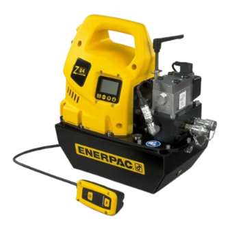
ZU4 Digital Torque Wrench Pump
CAUTION: Avoid damaging hydraulic hose. Avoid
sharp bends and kinks when routing hydraulic hoses.
Using a bent or kinked hose will cause severe back-pressure.
Sharp bends and kinks will internally damage the hose leading to
premature hose failure.
Do not drop heavy objects on hose. A sharp impact
may cause internal damage to hose wire strands.
Applying pressure to a damaged hose may cause it
to rupture.
IMPORTANT: Do not lift hydraulic equipment by the
hoses or swivel couplers. Use the carrying handle or
other means of safe transport.
CAUTION: Keep hydraulic equipment away from
flames and heat. Excessive heat will soften
packings and seals, resulting in fluid leaks. Heat also
weakens hose materials and packings. For optimum performance
do not expose equipment to temperatures of 150°F [65°C] or
higher. Protect hoses and cylinders from weld spatter.
DANGER: Do not handle pressurized hoses.
Escaping oil under pressure can penetrate the skin,
causing serious injury. If oil is injected under the skin,
see a doctor immediately.
WARNING: Only use hydraulic torque wrenches in a coupled
system. Never use a torque wrench with unconnected
couplers. If the torque wrench becomes extremely
overloaded, components can fail catastrophically causing severe
personal injury.
IMPORTANT: Hydraulic equipment must only be serviced
by a qualified hydraulic technician. For repair service,
contact the Authorized ENERPAC Service Center in your
area. To protect your warranty, use only ENERPAC oil
WARNING: Immediately replace worn or damaged parts
with genuine ENERPAC parts. Standard grade parts will
break causing personal injury and property damage.
ENERPAC parts are designed to fit properly and withstand high
loads.
1
Advertisement
Table of Contents

Related Manuals for Enerpac ZU4


Summary of Contents for Enerpac ZU4
- Page 1 Español ........15-28 Repair Parts Sheets for this product are available from the Enerpac web site at www.enerpac.com, or from your nearest Authorized...
-
Page 2: Pump Mounting
WARNING: These pumps have internal factory adjusted relief valves, which must not be repaired or adjusted except by an authorized Enerpac service center. WARNING: To prevent damage to pump electric motor, check specifications. Use of incorrect power source will damage the motor. -
Page 3: Operation
WARNING: When using pumps with multi-wrench manifolds, ensure all unused couplers have the protective caps fully installed before starting pump. Note: When the wrench is first connected to the pump, air will be Oil Fill trapped in the hydraulic circuit. Remove air by placing wrench Plug and straightened hoses below pump. -
Page 4: Pendant Operation
Choosing a unit of torque (Ft-lb or Nm) and turning Automode ON places the microcontroller in torque control mode. In this mode, the user selects from a list of Enerpac RSL torque wrench Connect power to pump. Using the LCD screen and keypad, models that are programmed into the microcontroller. -
Page 5: Lcd Menu Overview
• Torque Wrench Model Selection – (Available only if “Ft-lb” or button switches, and the additional button switches located on “Nm” is selected) Selects the model number of the Enerpac the pendant, all functions and settings described in sections 6.3 torque wrench to be used. - Page 6 Units menu (Section 6.5 B), a bar]. Save setting and step forward to the Main menu (See list of Enerpac RSL torque wrench Section. 6.5 H) by pressing the Menu button for 3 seconds. models will be shown on this screen.
- Page 7 6.5 G “Main” Menu 6.5 J “Low Volt” Menu (Ft-lb or Nm selected) (See Screen 10) This screen allows Screen 10 the operator to read the number of (See Screens 7A and 7B) If Automode LOW VOLT Screen 7A hours the pump has been operated in is ON, and a unit of torque has been RSL 2 a low-voltage condition.
- Page 8 80% of nominal voltage. buttons for 7 seconds. CAL PT A will appear on the LCD. While running the pump under this See Table 2, “ZU4 Pressure Transducer Calibration”, located condition, the “Low Voltage” signal will VOLTAGE near the end of this document.
-
Page 9: Maintenance
7.3 Motor Brush Replacement reduced voltage, provided that no fault conditions occur (See To prevent motor damage, the ZU4 motor brushes incorporate Section 6.6). The Low Voltage warning will automatically clear an automatic motor stop when one of the brush carbons wears once the low voltage condition has been resolved. -
Page 10: Troubleshooting Guide
9.0 TROUBLESHOOTING Only qualified hydraulic technicians should service the pump or system components. A system failure may or may not be the result of a pump malfunction. To determine the cause of the problem, the complete system must be included in any diagnostic procedure. -
Page 15: Precauciones De Seguridad
Las hojas de despiece para este producto están disponibles en la página web de Enerpac en www.enerpac.com, o en su Centro de Servicio Autorizado de Enerpac o en el punto de venta de Enerpac más cercano. 1.0 IMPORTANTES INSTRUCCIONES DE RECEPCIÓN Inspeccione visualmente todos los componentes para verificar si hay daños de envío. -
Page 16: Instalación
Caudal y corriente vs. Presión (metric) debe ser realizado por un técnico hidráulico cualificado. Para reparaciones, comuníquese con el Centro de Servicio 11,5 Autorizado de ENERPAC en su región. Use únicamente aceite de ENERPAC a fin de proteger su garantía. ADVERTENCIA: Sustituya inmediatamente las piezas desgastadas o dañadas por piezas originales de ENERPAC. -
Page 17: Conexiones Eléctricas
4.4 Conexiones eléctricas ADVERTENCIA: La bomba está equipada de fábrica con el enchufe eléctrico normal para un determinado voltaje. La modificación del tipo de enchufe sólo debe hacerla un electricista cualificado, cumpliendo todos los códigos aplicables locales y nacionales. La desconexión y la protección del circuito de línea serán proporcionadas por el cliente. - Page 18 Válvula de la bomba Llave dinamométrica Retroceso 700 BAR/10,000 PSI MAX. Avance 700 BAR/10,000 PSI MAX. Figura 5, Detalles de la manguera Parar el motor pulsando la tecla on/off del control remoto o la tecla on/off (Motor) de la funda). Si no se pulsan teclas del Tirar para control remoto o de la funda durante un periodo continuo de desacoplar.
- Page 19 Automode ON se pone al microcontrolador en modo control de control remoto, pueden activarse todas las funciones y todos par. En este modo, el usuario selecciona de una lista de Enerpac los ajustes que se describen en las secciones 6.3 a 6.5 de este modelos de llaves dinamométricas RSL programadas en el...
- Page 20 Guardar el ajuste establecido y pulsar sólo si está seleccionado “Ft-lb” o “Nm”) Selecciona el número la tecla Menu para continuar. Véase el de modelo de la llave dinamométrica de Enerpac que debe cuadro de referencia rápida (QRC), paso #2. utilizarse.
- Page 21 6.5 D Menú “Automode” mantener pulsada cualquier tecla para desplazarse rápidamente por los ajustes disponibles. El valor de la presión máxima es (Véase la Pantalla 4) Cambiar Automode Pantalla 4 10,000 psi [700 bar]. Guardar el ajuste y avanzar al menú Main ON u OFF pulsando la tecla de flecha AUTOMODE (Principal) (véase la Sección 6.5 H) pulsando la tecla Menu...
- Page 22 ______________________________________________________ 6.5 N Menú “Language” (Idioma) Nota general para todas las pantallas de horas y ciclos: (Véase la Pantalla 14) Esta pantalla Pantalla 14 permite al operario cambiar el idioma HORAS EN PANTALLA ESPANOL de la pantalla LCD. Cuando en la LCD - hasta 9999,9 la pantalla mostrará...
-
Page 23: Mantenimiento
Sección 6.6 A. CAL PT A. Véase la Tabla 2, “Calibración del transductor de presión ZU4”, 6.7 Advertencia en la LCD por Bajo Voltaje que se encuentra cerca del final de este documento. Seguir los pasos en la tabla para realizar los procedimientos de calibración. -
Page 24: Instalación De Accesorios
Figura 4. 7.3 Reemplazo de la escobilla del motor Para prevenir daño al motor, las escobillas del motor ZU4 incorporan una parada automática del motor cuando uno de los carbones de la escobilla se desgasta hasta una longitud de 0.25"... -
Page 25: Guía Para La Solución De Problemas
Guía para la solución de problemas* Problema Causa posible Acción La bomba no arranca. Condición de fallo. Véase la Sección 6.6, Condiciones de Fallo en la LCD. Escobillas del motor desgastadas hasta el final. Véase la Sección 7.3, Reemplazo de la Escobilla del Motor. El control remoto no Bomba en modo LOCAL.. - Page 32 www.enerpac.com...
Need help?
Do you have a question about the ZU4 and is the answer not in the manual?
Questions and answers