Table of Contents
Advertisement
EZ Switch 10/100/1000
Managed Ethernet Switch
◆ 24 auto-MDI/MDI-X 10/100/1000BASE-T ports
◆ 4 ports shared with 4 SFP transceiver slots
◆ Non-blocking switching architecture
◆ Up to eight LACP or static 8-port trunks
◆ Layer 2/3/4 CoS support through four priority queues
◆ Full support for VLANs
◆ IGMP multicast filtering and snooping
◆ Support for jumbo frames up to 9 KB
◆ Managed via the Web interface
Quick Installation Guide
SMCGS24C-Smart
Advertisement
Table of Contents

Related Manuals for SMC Networks SMCGS24C-Smart


Summary of Contents for SMC Networks SMCGS24C-Smart
- Page 1 ◆ Up to eight LACP or static 8-port trunks ◆ Layer 2/3/4 CoS support through four priority queues ◆ Full support for VLANs ◆ IGMP multicast filtering and snooping ◆ Support for jumbo frames up to 9 KB ◆ Managed via the Web interface Quick Installation Guide SMCGS24C-Smart...
-
Page 3: Installation Guide
EZ Switch 10/100/1000 Installation Guide From SMC’s EZ line of low-cost workgroup LAN solutions 38 Tesla Irvine, CA 92618 Phone: (949) 679-8000 April 2006 Pub. # 150000022600H... - Page 4 Information furnished by SMC Networks, Inc. (SMC) is believed to be accurate and reliable. However, no responsibility is assumed by SMC for its use, nor for any infringements of patents or other rights of third parties which may result from its use. No license is granted by implication or otherwise under any patent or patent rights of SMC.
-
Page 5: Limited Warranty
All SMC products carry a standard 90-day limited warranty from the date of purchase from SMC or its Authorized Reseller. SMC may, at its own discretion, repair or replace any product not operating as warranted with a similar or functionally equivalent product, during the applicable warranty term. - Page 6 RIGHTS, WHICH MAY VARY FROM STATE TO STATE. NOTHING IN THIS WARRANTY SHALL BE TAKEN TO AFFECT YOUR STATUTORY RIGHTS. * SMC will provide warranty service for one year following discontinuance from the active SMC price list. Under the limited lifetime warranty, internal and external power supplies, fans, and cables are covered by a standard one-year warranty from date of purchase.
-
Page 7: Japan Vcci Class A
OMPLIANCES FCC - Class A This equipment has been tested and found to comply with the limits for a Class A digital device, pursuant to part 15 of the FCC Rules. These limits are designed to provide reasonable protection against harmful interference when the equipment is operated in a commercial environment. -
Page 8: Ce Mark Declaration Of Conformance For Emi And Safety (Eec)
OMPLIANCES CE Mark Declaration of Conformance for EMI and Safety (EEC) SMC contact for these products in Europe is: SMC Networks Europe, Edificio Conata II, Calle Fructuós Gelabert 6-8, 2 08970 - Sant Joan Despí, Barcelona, Spain. This information technology equipment complies with the requirements of the Council... -
Page 9: Safety Compliance
Faserkabelenden schauen, während diese eingeschaltet sind. Power Cord Safety Please read the following safety information carefully before installing this switch: Warning: Installation and removal of the unit must be carried out by qualified personnel only. • The unit must be connected to an earthed (grounded) outlet to comply with international safety standards. - Page 10 OMPLIANCES Important! Before making connections, make sure you have the correct cord set. Check it (read the label on the cable) against the following: Power Cord Set U.S.A. and Canada Denmark Switzerland U.K. Europe The cord set must be UL-approved and CSA certified. The minimum specifications for the flexible cord are: - No.
-
Page 11: Veuillez Lire À Fond L'information De La Sécurité Suivante Avant D'installer Le Switch
Veuillez lire à fond l'information de la sécurité suivante avant d'installer le Switch: AVERTISSEMENT: L’installation et la dépose de ce groupe doivent être confiés à un personnel qualifié. • Ne branchez pas votre appareil sur une prise secteur (alimentation électrique) lorsqu'il n'y a pas de connexion de mise à... -
Page 12: Bitte Unbedingt Vor Dem Einbauen Des Switches Die Folgenden Sicherheitsanweisungen Durchlesen
OMPLIANCES Cordon électrique - Il doit être agréé dans le pays d’utilisation Suisse: Europe Bitte unbedingt vor dem Einbauen des Switches die folgenden Sicherheitsanweisungen durchlesen: WARNUNG: Die Installation und der Ausbau des Geräts darf nur durch Fachpersonal erfolgen. • Das Gerät sollte nicht an eine ungeerdete Wechselstromsteckdose angeschlossen werden. •... -
Page 13: Warnings And Cautionary Messages
Warning: This switch uses lasers to transmit signals over fiber optic cable. The lasers are compliant with the requirements of a Class 1 Laser Product and are inherently eye safe in normal operation. However, you should never look directly at a transmit port when it is powered on. -
Page 14: Manufacturing Materials
All printed documentation for this product uses biodegradable paper that originates from sustained and managed forests. The inks used in the printing process are non-toxic. Purpose This guide details the hardware features of this switch, including Its physical and performance-related characteristics, and how to install the switch. Audience This guide is for system administrators with a working knowledge of network management. -
Page 15: Table Of Contents
Overview ..........1-1 Switch Architecture ........1-2 Network Management Options . - Page 16 Displaying System Name ......5-12 Setting the Switch’s IP Address ......5-13 Configuring the Logon Password .
- Page 17 Troubleshooting ......A-1 Diagnosing Switch Indicators ....... . . A-1 Power and Cooling Problems .
- Page 18 ABLE OF ONTENTS German Instructions ......D-1 Eine Site Auswählen (Selecting a Site - German) ....D-1 Montage (Rack Mounting Instructions - German) .
- Page 19 Table 5-2 Switch Main Menu ........5-4...
- Page 20 Upgrade Firmware ......5-16 Figure 5-10 Restart Switch ....... . . 5-17 Figure 5-11 Register Product .
- Page 21 Figure 5-20 Trunk Configuration ......5-28 Figure 5-21 Trunk Rate Limiting ......5-29 Figure 5-22 LACP Port Configuration .
- Page 22 IGURES xviii...
-
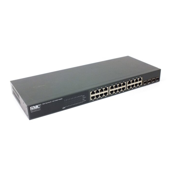
Page 23: Figure 1-1 Front Panels
EZ S Overview SMC’s EZ Switch 10/100/1000 SMC8024L2 is an intelligent Layer 2 switch with 24 10/100/1000BASE-T ports, four of which are combination ports that are shared with four SFP transceiver slots (see Figure 1-1, Ports 21-24). Port Status Indicators... -
Page 24: About The Ez Switch 10/100/1000
The switch employs a wire-speed, non-blocking switching fabric. This permits simultaneous wire-speed transport of multiple packets at low latency on all ports. The switch also features full-duplex capability on all ports, which effectively doubles the bandwidth of each connection. The switch uses store-and-forward switching to ensure maximum data integrity. -
Page 25: Description Of Hardware
(purchased separately) is installed in a slot and has a valid link on its port, the associated RJ-45 port is disabled and cannot be used. The switch can also be configured to force the use of an RJ-45 port or SFP slot, as required. -
Page 26: Power Supply Socket
1000 Mbps Condition Power Green Power Supply Socket The power socket is located on the rear panel of the switch. The standard 10/100/1000 13 14 15 16 17 18 19 20 21 22 23 24 Power Port Status LEDs Figure 1-3 Port LEDs and Power LED... -
Page 27: Features And Benefits
power socket is for the AC power cord. Features and Benefits Connectivity • 24 10/100/1000 Mbps ports for easy Gigabit Ethernet integration and for protection of your investment in legacy LAN equipment. • Auto-negotiation enables each RJ-45 port to automatically select the optimum communication mode (half or full duplex) if this feature is supported by the attached device;... -
Page 28: Expandability
• Jumbo-Frame up to 9,6 Kbytes • Supports flow control • Broadcast storm control Management • “At-a-glance” LEDs for easy troubleshooting. • Network management agent • Manages switch in-band or out-of-band • Supports web-based interface 10/100/1000... -
Page 29: Network Planning
When networks are based on repeater (hub) technology, the distance between end stations is limited by a maximum hop count. However, a switch turns the hop count back to zero. So subdividing the network into smaller and more manageable segments, and linking them to the larger network by means of a switch, removes this limitation. -
Page 30: Application Examples
You can easily build on this basic configuration, adding direct full- duplex connections to workstations or servers. When the time comes for further expansion, just connect to another hub or switch using one of the Gigabit Ethernet ports built into the front panel, a Gigabit Ethernet port on a plug-in SFP transceiver. -
Page 31: Central Wiring Closet
Central Wiring Closet With 24 parallel bridging ports (i.e., 24 distinct collision domains), this switch can collapse a complex network down into a single efficient bridged node, increasing overall bandwidth and throughput. In the figure below, the 1000BASE-T RJ-45 ports on the switch are providing 1 Gbps full-duplex connections for up to 24 local segments. -
Page 32: Remote Connections With Fiber Cable
A 1000BASE-SX (MMF) link can connect to a site up to 550 meters away, a 1000BASE-LX (SMF) link up to 5 km, and a 1000BASE-ZX link up to 100 km. This allows a switch stack to serve as a collapsed backbone, providing direct connectivity for a widespread LAN. -
Page 33: Making Vlan Connections
Making VLAN Connections The switch supports VLANs that can be used to organize any group of network nodes into separate broadcast domains. VLANs confine broadcast traffic to the originating group, and can eliminate broadcast storms in large networks. This provides a more secure and cleaner network environment. -
Page 34: Application Notes
1. Full-duplex operation only applies to point-to-point access (such as when a switch is attached to a workstation, server or another switch). When the switch is connected to a hub, both devices must operate in half-duplex mode. 2. For network applications that require routing between dissimilar network types, you can attach the switch directly to a multi-protocol router. -
Page 35: Installing The Switch
NSTALLING THE Selecting a Site EZ Switch 10/100/1000 units can be mounted in a standard 19-inch equipment rack or on a flat surface. Be sure to follow the guidelines below when choosing a location. • The site should: - be at the center of all the devices you want to link and near a power outlet. -
Page 36: Ethernet Cabling
1000BASE-T. • Protection from radio frequency interference emissions • Electrical surge suppression • Separation of electrical wires (switch related or other) and electromagnetic fields from data based network wiring • Safe connections with no damaged cables, connectors or shields RJ-45 Connector... -
Page 37: Equipment Checklist
• Power cord—either US, Continental Europe or UK • This Installation Guide • User Guide CD • SMC Warranty Registration Card—be sure to complete and return to Optional Rack-Mounting Equipment If you plan to rack-mount the switches, be sure to have the following equipment available: •... -
Page 38: Rack Mounting
NSTALLING THE WITCH Rack Mounting Before rack mounting the switch, pay particular attention to the following factors: • Temperature: Since the temperature within a rack assembly may be higher than the ambient room temperature, check that the rack-environment temperature is within the specified operating temperature range (see page C-2). -
Page 39: Figure 3-2 Attaching The Brackets
1. Attach the brackets to the device using the screws provided in the Bracket Mounting Kit. Figure 3-2 Attaching the Brackets 2. Mount the device in the rack, using four rack-mounting screws (not provided). Figure 3-3 Installing the Switch in a Rack OUNTING... -
Page 40: Desktop Or Shelf Mounting
2. Set the device on a flat surface near an AC power source, making sure there are at least two inches of space on all sides for proper air flow. 3. If installing a single switch only, go to “Connecting to a Power Source” at the end of this chapter. -
Page 41: Installing An Optional Sfp Transceiver Into The Switch
NSTALLING AN Installing an Optional SFP Transceiver into the Switch Figure 3-5 Inserting an SFP Transceiver into a Slot The switch supports the following optional transceivers: Table 3-1 Optional Transcievers 1000BASE-SX (SMCBGSLCX1) 1000BASE-LX (SMCBGLLCX1) 1000BASE-ZX (SMCBGZLCX1) To install an SFP transceiver, do the following: 1. -
Page 42: Connecting To A Power Source
NSTALLING THE WITCH Note: SFP transceivers are hot-swappable. The switch does not need to be powered off before installing or removing a transceiver. However, always first disconnect the network cable before removing a transceiver. Note: SFP transceivers are not provided in the switch package. -
Page 43: Making Network Connections
Connecting Network Devices The EZ Switch 10/100/1000 units are designed to interconnect multiple segments (or collision domains). It can be connected to network cards in PCs and servers, as well as to hubs, switches or routers. It may also be connected to devices using optional SFP transceivers. -
Page 44: Connecting To Pcs, Servers, Hubs And Switches
Figure 4-1 Making Twisted-Pair Connections 2. If the device is a PC card and the switch is in the wiring closet, attach the other end of the cable segment to a modular wall outlet that is connected to the wiring closet. (See “Network Wiring Connections”... -
Page 45: Network Wiring Connections
1. Attach one end of a patch cable to an available port on the switch, and the other end to the patch panel. 2. If not already in place, attach one end of a cable segment to the back of the patch panel where the punch-down block is located, and the other end to a modular wall outlet. -
Page 46: Fiber Optic Sfp Devices
50/125 or 62.5/125 micron multimode fiber optic cabling with an LC connector at both ends. Warning: the switch use lasers to transmit signals over fiber optic cable. The lasers are compliant with the requirements of a Class 1 Laser Product and are inherently eye safe in normal operation. -
Page 47: Figure 4-3 Making Connections To Sfp Transceivers
3. Connect one end of the cable to the LC port on the switch and the other end to the LC port on the other device. Since LC connectors are keyed, the cable can be attached in only one orientation. -
Page 48: Connectivity Rules
However, note that because switches break up the path for connected devices into separate collision domains, you should not include the switch or connected cabling in your calculations for cascade length involving other devices. -
Page 49: Mbps Fast Ethernet Collision Domainn
Table 4-3 Maximum 1000BASE-LX Fiber Optic Cable Length Fiber Diameter 9/125 micron single-mode fiber Table 4-4 Maximum 1000BASE-ZX Fiber Optic Cable Length Fiber Diameter 9/125 micron single-mode fiber * For link spans exceeding 70 km, you may need to use premium single mode fiber or dispersion shifted single mode fiber 100 Mbps Fast Ethernet Collision Domain Table 4-5 Maximum Fast Ethernet Cable Length... -
Page 50: Cable Labeling And Connection Records
For each piece of equipment, identify the devices to which it is connected. • Note the length of each cable and the maximum cable length supported by the switch ports. • For ease of understanding, use a location-based key when assigning prefixes to your cable labeling. -
Page 51: Configuring The Switch
(Internet Explorer 5.5 or above, or Mozilla Firefox 1.0 or above). Prior to accessing the switch from a web browser, be sure you have first performed the following tasks: 1. Configure the switch with a valid IP address, subnet mask, and default gateway. -
Page 52: Navigating The Web Browser Interface
To access the web-browser interface you must first enter a password. The user has Read/Write access to all configuration parameters and statistics. The default password for the switch is “smcadmin.” If user input is not detected within five minutes, the current session will be terminated. -
Page 53: Configuration Options
“Every visit to the page.” Panel Display The web agent displays an image of the switch’s ports. The port will turn green when the corresponding front-panel port is in connection with another device. To show the port number, place mouse pointer onto the intended port. -
Page 54: Main Menu
ONFIGURING THE WITCH Main Menu Using the onboard web agent, you can define system parameters, manage and control the switch, and all its ports, or monitor network conditions. The following table briefly describes the selections available from this program. Menu... - Page 55 Configures trunk connection settings Sets the rate limiting parameters for each Trunk configured on the Switch. Sets VLAN group. Configures the VLANs on the switch for both Ports and Trunks. Sets the priority of packets within the switch. Setus up IP filter.
-
Page 56: Web Configuration
Field Attributes System Information • System Name – Name assigned to the switch system. • Number of Ports – Number of built-in ports. • Hardware Version – Hardware version of the main board. • Code Version – Version number of the code. - Page 57 • Trunk – The trunk label. "T1" through "T8" are used as trunk labels. • Type – All trunks and ports on this switch are 10/100/1000M • Trunk Status – An indication of the speed and duplex setting of the trunk.
-
Page 58: Figure 5-3 Switch Information
ONFIGURING THE WITCH Web – Click STATUS, Overview. Figure 5-3 Switch Information... -
Page 59: Showing Port Statistics
Showing Port Statistics You can display statistics on network traffic from the ports. These statistics can be used to identify potential problems with the switch (such as a faulty port or unusually heavy loading). All values displayed have been accumulated since the last system reboot, but can be reset to zero by clicking the CLEAR button. - Page 60 ONFIGURING THE WITCH Parameter Received Broadcast Packets Transmitted Octets Transmitted Unicast Packets Transmitted Errors Received Normal Priority Packets Transmitted Normal Priority Packets RMON Statistics Drop Events Received Frames Multicast Frames Undersize Frames Fragments Collisions 5-10 Table 5-3 Port Statistics (Continued) Description The number of packets, delivered by this sub-layer to a higher (sub-)layer, which were addressed to a...
- Page 61 Table 5-3 Port Statistics (Continued) Parameter Received Bytes Broadcast Frames CRC/Alignment Errors Oversize Frames Jabbers 64 Bytes Frames 65-127 Byte Frames 128-255 Byte Frames 256-511 Byte Frames 512-1023 Byte Frames 1024-1518 Byte Frames Description Total number of bytes of data received on the network.
-
Page 62: Displaying System Name
ONFIGURING THE WITCH Web – Click STATUS, Statistics. Displaying System Name You can easily identify the system by displaying the device name. Field Attributes • Switch Name – Name assigned to the switch system. 5-12 Figure 5-4 Port Statistics... -
Page 63: Setting The Switch's Ip Address
Setting the Switch’s IP Address This section describes how to configure an IP interface for management access over the network. The IP address for this switch is 192.168.2.10 by default. To manually configure an address, you need to change the switch’s default settings (IP address 192.168.2.10 and netmask 255.255.255.0) to... -
Page 64: Manual Configuration
ONFIGURING THE WITCH Manual Configuration Web – Click System, LAN Settings. Enter the IP address, subnet mask and gateway, then click APPLY. Configuring the Logon Password The administrator has write access for all parameters governing the onboard agent. You should therefore assign a new administrator password as soon as possible, and store it in a safe place. -
Page 65: Tools
APPLY. Figure 5-7 Password Settings Tools On Tools page, you can restore the switch to default settings, upgrade the firmware of the switch, or restart the switch. Restore to Factory Defaults Force the Switch to restore the original factory settings. To reset the switch, select "Reset to Factory Defaults"... -
Page 66: Figure 5-8 Reset To Factory Defaults
Web – Click System, Tools, Reset to Factory Defaults. Upgrade Firmware Upgrades the Switch system firmware using a file provided by SMC. Select "Upgrade Firmware" from the Tools drop-down list then click on the "Browse" button to select the firmware file. Finally, press the APPLY button to upgrade the selected Switch firmware file. -
Page 67: Upload/Download Configuration
"Download", and then click on the "Browse" button to select the file. Restart Switch Web – Click SYSTEM, Tools, Restart Switch. To restart the switch, select from the Tools drop-down list, and then click APPLY. The reset will be complete when the user interface displays the login page. -
Page 68: Register Product
Register Product Register your product if you have not already done so. Web – Click System, Register Product. By clicking the Register Now button you will be taken to the SMC website, where you can enter the products details. Static MAC A static MAC address is an entry in MAC table which can not be aged out. -
Page 69: Counter Config
ONFIGURATION Web – Click System, Static MAC. Figure 5-12 Static MAC Address Configuration Counter Config This page allows the customer to select the statistics to count and display. It is possible to monitor 5 Transmit counters,5 receive counters as well as 1 transmit byte counter and receive byte counter at the same time. -
Page 70: Port Configuration
ONFIGURING THE WITCH Web – Click PORTS, Settings. Port Configuration You can use the Port Configuration page to manually fix the speed, duplex mode, and flow control. Field Attributes • Speed/Duplex – Allows you to manually set the port speed and duplex mode. -
Page 71: Configuring Rate Limits
Rate limiting is configured on interfaces at the edge of a network to limit traffic into or out of the switch. Traffic that falls within the rate limit is transmitted, while packets that exceed the acceptable amount of traffic are dropped. -
Page 72: Figure 5-15 Rate Limiting
Web – Click PORTS, Rate Limiting. This page enables you to set the rate limiting parameters for each port on the Switch. 5-22 Figure 5-15 Rate Limiting... -
Page 73: Storm Control
• Rate(number of frame per second) – The Rate field is set by a single drop-down list. The same threshold is applied to every port on the switch. When the threshold is exceeded, packets are dropped, irrespective of the flow-control settings. -
Page 74: Port Mirroring
WITCH Web – Click PORTS, Storm Control. This page enables you to set the broadcast storm control parameters for every port on the Switch. Port Mirroring You can mirror traffic from any source port to a target port for real-time analysis. -
Page 75: Cable Diagnostic
If the total ingress bandwidth exceeds the mirror port's egress bandwidth, packets will eventually be dropped on ingress to the switch which means they will not reach the mirror port or their intended destination port. Input rate-limiting in conjunction with port flow-control could be used to ensure that the total ingress bandwidth never exceeds the egress bandwidth. -
Page 76: Trunks Membership
ONFIGURING THE WITCH cabling. Web – Click PORTS, Port Mirroring. Trunks Membership This page allows you to create a maximum of eight trunks of up to eight ports each. The Membership Table has one row for each port and ten columns. -
Page 77: Trunk Configuration
• Trunk T1-T8 – These columns correspond to the eight trunks that are supported by the Switch. Clicking on the radio button in any one of these columns causes the port to become a member of the corresponding trunk. Web – Click TRUNKS, Membership. Click to select which Trunk member to which each port belongs. -
Page 78: Trunk Rate Limit
Web – Click TRUNKS, Settings. Trunk Rate Limit This page allows you to change the maximum data-rate into and out of each trunk on the switch. Field Attributes • Trunk – Indicates trunk identification. • Trunk Speed – Indicates the trunk speed. -
Page 79: Vlan Settings
VLAN settings in the default configuration. The default configuration is as follows: • All ports are members of VLAN 1 • The switch management interface is on VLAN 1 (this cannot be changed) • All ports have a Port VLAN ID (PVID) of 1... - Page 80 There are three different parameters that can be configured for each port on the switch; VLAN IDs (VLAN membership), PVID and Packet Type. Note that the ports within a Trunk cannot be configured individually; configure the Trunk instead (Trunks are labelled T1 to T8).
- Page 81 to “All”. PCs cannot, in general, send or receive tagged packets. Switches should be connected to each other with Packet Type set to “Tagged”. If the Packet Type is set to “All”, the port can accept incoming tagged and untagged packets. Untagged packets will be associated with the VLAN identified by the PVID.
-
Page 82: Qos Settings
QoS (Quality of Service) is a mechanism which is used to prioritize certain traffic as it is moves through the switch. Traffic can be classified as High or Normal priority and, when the switch is heavily loaded, it is the Normal priority packets that are dropped first. - Page 83 ONFIGURATION DSCP Packets are prioritized using the DSCP (Differentiated Services Code Point) value. The Differentiated Services Code Point (DSCP) is a six bit field that is contained within an IP (TCP or UDP) header. Six bits allows the DSCP field to take any value in the range 0 - 63 inclusive. When QoS Mode is set to DSCP, the DSCP Configuration table appears which allows a priority (normal or high) to be set for each of the DSCP values.
-
Page 84: Security
ONFIGURING THE WITCH Security IP Filter On this page, you can setup the source IP Filter on all or some ports. It is used to block unwanted access and provide access to the network for either a specific source IP address or a specific subnet. The IP Filter Configuration table has one row for each port and five columns. - Page 85 • Static - Enable source IP filter with configured values in IP Address and IP Mask fields. • DHCP - The IP address for the device connected to this port will be automatically assigned by DHCP server and only frames with the assigned IP address are allowed to access the network.
- Page 86 The Port Security table has one row for each port and five columns. When port security is enabled on a port, the switch stops learning new MAC addresses on the specified port when it has reached a configured maximum number.
- Page 87 • Send Trap and Deny New Stations - Besides denying the new station, trap message is sent by the switch to report an intrusion action. • Trunk - Display the trunk ID if the port is member of a trunk group.
-
Page 88: Figure 5-26
WITCH Web – Click Security, Port Cecurity. This page enables you to setup management access filter on the switch. With the Management Access Filter Configuration table, you can create a list of up to 8 IP addresses or IP address groups that are allowed management access to the switch through the web interface. -
Page 89: Igmp Snoop
Settings Field Attributes IGMP Snooping Configuration • IGMP Enabled - When enabled, the switch will monitor network traffic to determine which hosts want to receive multicast traffic. • Router Ports - Set if ports are conneting to the IGMP administrative routers. - Page 90 ONFIGURING THE WITCH • Unregistered IPMC Flooding enabled - Set forwarding mode for unregistered (not-joined) IP multicast traffic. The traffic will flood when enabled, and forward to router-ports only when disabled. IGMP Snooping VLAN Configuration • VLAN ID - The VLAN ID. It can not be changed. •...
-
Page 91: Igmp Snoop
ONFIGURATION IGMP Status Show the IGMPSNOOP statistics for the whole switch. Field Attributes • VLAN ID - VLAN ID number. • Querier - Show whether Querying is enabled. • Queries transmitted - Show the number of transmitted Query packets. • Queries received - Show the number of received Query packets. - Page 92 ONFIGURING THE WITCH 5-42...
-
Page 93: Troubleshooting
Contact SMC Technical Support. • Verify that the switch and attached device are powered • Be sure the cable is plugged into both the switch and corresponding device. • If the switch is installed in a rack, check the connections to the punch-down block and patch panel. -
Page 94: Power And Cooling Problems
Then verify that you entered the correct IP address. Also, be sure the port through which you are connecting to the switch has not been disabled. If it has not been disabled, then check the network cabling that runs between your remote location and the switch. -
Page 95: Cables
Twisted-Pair Cable and Pin Assignments For 10BASE-T/100BASE-TX connections, a twisted-pair cable must have two pairs of wires. For 1000BASE-T connections the twisted-pair cable must have four pairs of wires. Each wire pair is identified by two different colors. For example, one wire might be green and the other, green with white stripes. -
Page 96: 10Base-T/100Base-Tx Pin Assignments
1, 2, 3, and 6, at one end of the cable, are connected straight through to pins 1, 2, 3, and 6 at the other end of the cable. When using any RJ-45 port on the switch, you can use either straight-through or crossover cable. -
Page 97: Twisted-Pair Cable And Pin Assignments
(MDI-X), the two pairs of wires must be straight-through. (When auto-negotiation is enabled for any RJ-45 port on the switch, you can use either straight-through or crossover cable to connect to any device type.) You must connect all four wire pairs as shown in the following diagram to support Gigabit Ethernet connections. -
Page 98: Crossover Wiring
“X” (which indicates MDI), a crossover must be implemented in the wiring. (When auto-negotiation is enabled for any RJ-45 port on the switch, you can use either straight-through or crossover cable to connect to any device type.) You must connect all four wire pairs as shown in the following diagram to support Gigabit Ethernet connections. -
Page 99: 1000Base-T Pin Assignments
1000BASE-T Pin Assignments All 1000BASE-T ports support automatic MDI/MDI-X operation, so you can use straight-through cables for all network connections to PCs or servers, or to other switches or hubs. The table below shows the 1000BASE-T MDI and MDI-X port pinouts. These ports require that all four pairs of wires be connected. -
Page 100: Adjusting Existing Category 5 Cabling To Run 1000Base-T
ABLES Note that when testing your cable installation, be sure to include all patch cables between switches and end devices. Adjusting Existing Category 5 Cabling to Run 1000BASE-T If your existing Category 5 installation does not meet one of the test parameters for 1000BASE-T, there are basically three measures that can be applied to try and correct the problem: 1. -
Page 101: Specifications
Physical Characteristics Ports 20 10/100/1000BASE-T, with auto-negotiation 4 10/100/1000BASE-T shared with 4 SFP transceiver slots. Network Interface Ports 1-24/48: RJ-45 connector, auto MDI/X 10BASE-T: RJ-45 (100-ohm, UTP cable; Category 3 or better) 100BASE-TX: RJ-45 (100-ohm, UTP cable; Category 5 or better) 1000BASE-T: RJ-45 (100-ohm, UTP or STP cable;... -
Page 102: Switch Features
Power Supply Internal, auto-ranging transformer: 100 to 240 VAC, 50 to 60 Hz Power Consumption 28 Watts Maximum Current 0.25 A @ 115 VAC 0.12 A @ 230 VAC Switch Features Forwarding Mode Store-and-forward Throughput Wire speed Management Features In-Band Management... -
Page 103: Standards
Software Loading TFTP in-band Standards IEEE 802.3-2002 Ethernet, Fast Ethernet, Gigabit Ethernet IEEE D802.1Q Virtual LAN IEEE 802.1X, Port-Based Network Access Control, 2001 ISO/IEC 8802-3 Compliances CE Mark Emissions FCC Class A VCCI Class A Immunity EN 61000-4-2/3/4/5/6/8/11 Safety CSA/NRTL (UL60950-1,CSA60950-1) TÜV/GS (EN60950-1) CB (IEC60950-1) Warranty... - Page 104 PECIFICATIONS...
-
Page 105: German Instructions
ERMAN Eine Site Auswählen (Selecting a Site - German) Die Schalter können in ein Standard-19-Zoll-Ausrüstungsgestell oder auf eine flache Ebene montiert werden. Zum Auswählen eines Standortes beachten Sie bitte die nachstehenden Richtlinien. • Die Site sollte: Sich in der Mitte aller anzuschließenden Geräte sowie in der Nähe einer Netzsteckdose befinden;... -
Page 106: Montage (Rack Mounting Instructions - German
Fur alle Gerate wird empfohlen, einen Filter oder einen Überspannungsschutz zu verwenden. Montage (Rack Mounting Instructions - German) Switch-Einheiten können an ein standardmäßiges 19-Zoll Einrichtungsrack, einen Arbeitstisch oder ein Regal montiert werden. Folgend finden Sie die Montageanweisungen für jeden Positionstyp. - Page 107 Schrauben an dem Gerät. 2. Befestigen Sie das Gerät mit vier Rackmontageschrauben (nicht beigelegt) an dem Rack. 3. Wenn Sie nur einen Switch installieren, dann springen Sie bitte über zu "Verbinden mit einer Stromquelle" auf Seite 3-8 am Ende dieses Kapitels.
- Page 108 ONTAGE OUNTING NSTRUCTIONS ERMAN...
-
Page 109: Table E-1 Ez Switch 10/100/1000 Products And Accessories
RDERING Table E-1 EZ Switch 10/100/1000 Products and Accessories Product Number SMCGS24C-Smart SMCBGSLCX1 SMCBGLLCX1 SMCBGZLCX1 PPENDIX NFORMATION Description Smart Switch 24 port 10/100/1000 1-port 1000BASE-SX Small Form Pluggable (SFP) mini-GBIC transceiver 1-port 1000BASE-LX Small Form Pluggable (SFP) mini-GBIC transceiver 1-port 1000BASE-ZX Small Form Pluggable (SFP) -
Page 110: Ordering Information
RDERING NFORMATION... -
Page 111: Auto-Negotiation
10BASE-T IEEE 802.3 specification for 10 Mbps Ethernet over two pairs of Category 3 or better UTP cable. 100BASE-TX IEEE 802.3u specification for 100 Mbps Fast Ethernet over two pairs of Category 5 or better UTP cable. 1000BASE-LX IEEE 802.3z specification for Gigabit Ethernet over two strands of 50/125, 62.5/125 or 9/125 micron core fiber cable. - Page 112 LOSSARY Bandwidth The difference between the highest and lowest frequencies available for network signals. Also synonymous with wire speed, the actual speed of the data transmission along the cable. Collision A condition in which packets transmitted over the cable interfere with each other.
-
Page 113: Full Duplex
Full Duplex Transmission method that allows two network devices to transmit and receive concurrently, effectively doubling the bandwidth of that link. Gigabit Ethernet A 1000 Mbps network communication system based on Ethernet and the CSMA/CD access method. IEEE Institute of Electrical and Electronic Engineers. IEEE 802.3 Defines carrier sense multiple access with collision detection (CSMA/CD) access method and physical layer specifications. -
Page 114: Network Diameter
LOSSARY Layer 2 Data Link layer in the ISO 7-Layer Data Communications Protocol. This is related directly to the hardware interface for network devices and passes on traffic based on MAC addresses. Light emitting diode used for monitoring a device or network condition. Link Segment Length of twisted-pair or fiber cable joining a pair of repeaters or a repeater and a PC. -
Page 115: Virtual Lan (Vlan)
Redundant Power Supply (RPS) A backup power supply unit that automatically takes over in case the primary power supply should fail. RJ-45 Connector A connector for twisted-pair wiring. Switched Ports Ports that are on separate collision domains or LAN segments. Telecommunications Industry Association Transmission Control Protocol/Internet Protocol (TCP/IP) Protocol suite that includes TCP as the primary transport protocol, and IP... - Page 116 LOSSARY Glossary-6...
-
Page 117: Index
Numerics 10 Mbps connectivity rules 4-7 100 Mbps connectivity rules 4-7 1000 Mbps connectivity rules 4-6 1000BASE-LX fiber cable lengths 4-7 1000BASE-SX fiber cable lengths 4-6 1000BASE-T pin assignments B-5 ports 1-3 1000BASE-ZX fiber cable lengths 4-7 100BASE-TX cable lengths 4-7 ports 1-3 10BASE-T ports 1-3 10BASE-T/100BASE-TX pin... - Page 118 NDEX IEEE 802.3z Gigabit Ethernet 1-5 indicators, LED 1-3 installation connecting devices to the switch 4-2 desktop or shelf mounting 3-6 port connections 4-1 power requirements 3-1 problems A-2 rack mounting 3-4 site requirements 3-1 wiring closet connections 4-7 IP address...
- Page 119 5-9 status LEDs 1-3 surge suppressor, using 3-1 switch architecture 1-2 switching, introduction to 2-1 temperature within a rack 3-4 troubleshooting in-band access A-2 power and cooling problems A-2 switch indicators A-1 twisted-pair connections 4-1 user password 5-14...
- Page 120 NDEX Index-4...
- Page 122 North West Africa: CIS: PRC: Taiwan: Asia Pacific: Korea: Japan: Australia: India: If you are looking for further contact information, please visit www.smc.com, www.smc-europe.com, or www.smc-asia.com. 38 Tesla Irvine, CA 92618 Phone: (949) 679-8000 (800) SMC-4-YOU; Fax (949) 679-1481 34-91-352-00-40; Fax 34-93-477-3774 44 (0) 1932 866553;...
Need help?
Do you have a question about the SMCGS24C-Smart and is the answer not in the manual?
Questions and answers