UTEPO UTP3-SW04-TP60 - 4 Ports PoE Ethernet Switch Manual
- User manual (2 pages)
Advertisement
Introduction
4 ports PoE Ethernet Switch is a high definition surveillance and security system. The product fully combines the characteristics of security surveillance, provides fast packet forwarding ability and abundant backplane bandwidth, which ensures clear image and fluent transmission. ESD and surge protection circuit can improve product stability. The product supports one key CCTV model, with function can restrain the nentwork storm, protect the information security, prevent the viral transmission and cyber attack, fully satisfy the Ethernet video security surveillance system and Ethernet project needs.

Feature
- Major ports: 1pcs*100Mbps uplink Ethernet port, 4pcs*100Mbps downlink Ethernet ports, every port supports MDI/MDIX;
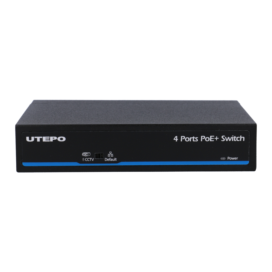
- Special function: One key CCTV model 1 4; ~ downlink ports can only communicate with uplink ports;
- Power input: DC48V~57V;
- Transmission Distance: Ethernet port 0~100m; the furthest transmission distance could reach 250m in CCTV model; Uplink port can reach 100m;
- Standard: Meet IEEE802.3,IEEE802.3u, IEEE802.3 af/at standards, PoE use End-Span, the spare cable can be of other use;
- Protection: Excellent anti-thunder, anti-static and anti-interference ability;
- Appearance: Delicate design and easy installation, configure the anti-theft lock hole, guard against theft;
- Operation: Plug and Play, No Setting required.
 Notice
The transmission distance is related to the connected cable. We suggest standard Cat5e/6 network cable, so the transmission distance can up tofurthest!
Board Diagram

Notice
- Device must be connected with lightning protection grounding; otherwise protection level will reduce; please use above No.20 wire to connect the grounding terminal.
- Turn the dial switch for left, the equipment can enter surveillance module after providing equipment power.
Installation steps
Please check the following items before installation, if it is missing, please contact the dealer.
| 1pcs |
| 1pcs |
| 1pcs |
| 1pcs |
| 1pcs |
Please follow the below installation steps
- Please turn off the signal power and display device power before installation, or it will damage the transmission equipment;
- Use network cable connect PoE IP camera and 1~4 downlink ports of product respectively;
- Use a network cable connect equipment uplink port and NVR or computer;
- Connect power adapter;
- Check if the installation is correct, equipment is in good condition, the connection is stable, then power on for system;
- Ensure the Ethernet equipment with power on can work properly.
Specification
| Item | Description | ||||
| Power | Power Supply | Power Adaptor | |||
| Voltage Range | DC48V~54V | ||||
| Consumption | |||||
| Ethernet | Speed | 1-4 port: Default: 10/100Mbps; CCTV:10Mbps; UPLINK:100Mbps | |||
| Transmission Distance | 1-4 port: Default: 0~100m; CCTV:0~250m; UPLINK:100m | ||||
| Network Switch | Ethenet Standard | IEEE 802.3/802.3u/802.3af/at | |||
| Backplane Bandwidth | 1.0G | ||||
| Packet Forwarding Rate | 0.75Mbps | ||||
| Packet Buffer | 768K | ||||
| MAC | 2K | ||||
| Status Indicator | Power Light | 1pcs(Red ) | |||
| Ethernet Port Light | 2pcs(Yellow&Green) on RJ45,yellow indicates PoE, green indicates Link/Act | ||||
| Surveillance Module Light | 1pcs(Green), green indicates CCTV | ||||
| Protection Level | Pluse Group | Level 2 Standard: IEC61000-4-4 | |||
| ESD | 1a Contact Discharge Level 3 1b Air Discharge Level 3 Standard: IEC61000-4-2 | ||||
| Anti-thunder Level | Level Standard 3: IEC61000-4-5 | ||||
| Working Environment | Working Temperature | 0 ~55℃ ℃ | |||
| Storage Temperature | -40 ~85℃ ℃ | ||||
| Humidity(Non-condesing) | 0~95% | ||||
| Mechanical | Dimension(L*W*H) | 135mm×85.6mm×27mm | |||
| Out Shell | Galvanized Sheet | ||||
| Color | Black | ||||
| Weight | 315g | ||||
| Power/Distance 54V | Distance | 100m | 150m | 200m | 250m |
| Power | 26W | 24W | 23W | 21W | |
Specification change will not be noticed
Trouble Shooting
Please follow the steps if the equipment has trouble.
- Make sure the equipment is installed according to the manufactures installation guide.
- Confirm RJ45 cable order meets EIA/TIA568A or 568B standard.
- Every PoE port can provide PoE equipment maximum power less than 30W, please do not connect the PoE equipment with power over 30W.
- Replace the equipment with a proper functioning 4 ports PoE Ethernet Switch to check if the equipment is damaged.
- Please contact your vendor if trouble still exists.
Plug Producing Method
Instruments to be used: wire crimper, network tester. Wire sequence of RJ45 plug should conform with EIA/TIA568A or 568B.

- Please remove 2cm long the insulating layer, and bare 4 pairs UTP cable;
- Separate the 4 pairs UTP cable and straighten them;
- Line up the 8 pieces of cables per EIA/TIA 568A or 568B;
- Cut off the cables to leave 1.5cm bare wire;
- Plug 8 cables into RJ45 plug, make sure each cable is in each pin;
- Use the wire crimper to crimp it;
- Repeat above 5 steps to make the another end;
- Use network tester to test the cable if it works.
Notice
When choose RJ45 make sure if one end is EIA/TIA568A,the other end should also be EIA/TIA568A.
When choose RJ45 make sure if one end is EIA/TIA568B,the other end should also be EIA/TIA568B.
Documents / ResourcesDownload manual
Here you can download full pdf version of manual, it may contain additional safety instructions, warranty information, FCC rules, etc.
Download UTEPO UTP3-SW04-TP60 - 4 Ports PoE Ethernet Switch Manual
Advertisement


Need help?
Do you have a question about the UTP3-SW04-TP60 and is the answer not in the manual?
Questions and answers