Advertisement
Quick Links
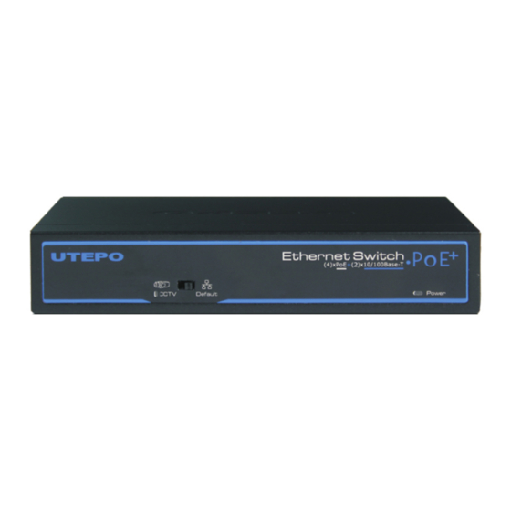
4 Ports PoE Ethernet Switch
User Manual
4 ports PoE Ethernet Switch is a surveillance security Ethernet Switch which aims at Ethernet
high definition surveillance, Ethernet project security system. The product fully combines the
characteristic of surveillance security, provides fast packet forwarding ability and abundant
backplane bandwidth, which ensures clear image and fluent transmission. ESD and surge
protection circuit can improve product stability. The product supports one key CCTV model,
can achieve VLAN, control the Net storm, protect the information security, prevent the viral
transmission and Ethernet attack, fully satisfy the Ethernet video surveillance security system
and Ethernet project needs.
Application
Feature
● Major ports: 1 pcs 100Mbps uplink optical port, 4 pcs 100Mbps down link Ethernet
ports , every port supports MDI/MDIX;
● Special function: One key CCTV model;1~4 downlink ports can only communicate
with uplink ports;
● Power input: DC48V~57V;
● Transmission Distance : Ethernet port 0~100m,the furthest transmission distance
could reach 250m in CCTV model; Optical port 20km;
● Standard: Meet IEEE802.3 ,IEEE802.3u,IEEE802.3 af/at standards, PoE use
End-Span, the spare cable can be of other use;
● Protection: Excellent anti-thunder, anti-static and anti-interference ability;
● Appearance: Delicate design and easy installation, configure the anti-theft lock hole,
guard against theft;
●Operation: Plug and Play, No Setting required.
Notice
The transmission distance is related to the connected cable. We suggest standard
Cat5e/6 network cable, so the transmission distance can up to furthest!
1
Board Diagram
Front board
VerB 1.3
Back board
Power input port
Side board
Notice
1
) Device must be connected with lightning protection grounding; otherwise protection
level will reduce; please use above No.20 wire to connect the grounding terminal.
2) Turn the dial switch for left, the equipment can enter surveillance mode after providing
equipment power.
Installation steps
Please check the following items before installation, if it is missing, please contact the
dealer .
4 ports PoE Ethernet Switch
Power adaptor
AC power cable
Accessory
User manual
Please follow the below installation steps
1) Please turn off the signal power and display device power before installation, installation
with power will damage the transmission equipment;
2) Use network cable connect PoE IP camera and 1~4 downlink ports of product respectively;
3) Use fiber connect equipment uplink optical port and uplink equipment's(optical converter)
optical port, please notice that the fiber port RX and TX need cross-linking .
4) Connect power adapter;
5) Check if the installation is correct, equipment is in good condition, the connection is stable,
then provide power for system;
6) Ensure the Ethernet equipment with power and work properly.
4 Ports PoE Ethernet Switch
CCTV mode
Power indicated light
Uplink Ethernet port
PoE down link
Ethernet port
Optical port
indicated light
Kensington lock
1pc
1pc
1pc
1pc
1pc
Ground
2
Advertisement

Summary of Contents for UTEPO UTP3-SW04-FP60
- Page 1 4 Ports PoE Ethernet Switch 4 Ports PoE Ethernet Switch Board Diagram User Manual Front board VerB 1.3 4 ports PoE Ethernet Switch is a surveillance security Ethernet Switch which aims at Ethernet high definition surveillance, Ethernet project security system. The product fully combines the characteristic of surveillance security, provides fast packet forwarding ability and abundant backplane bandwidth, which ensures clear image and fluent transmission.
- Page 2 4 Ports PoE Ethernet Switch 4 Ports PoE Ethernet Switch 连接接口 连接接口 Specification Trouble Shooting Please follow the steps if the equipment has trouble. Item Description Make sure the equipment is installed according to the manufactures installation guide. Power Supply Power Adaptor Confirm RJ45 cable order meets EIA/TIA568A or 568B standard.


Need help?
Do you have a question about the UTP3-SW04-FP60 and is the answer not in the manual?
Questions and answers