Table of Contents
Advertisement
Quick Links
Advertisement
Table of Contents

Related Manuals for OpenEye OE-C9112F12


Summary of Contents for OpenEye OE-C9112F12
- Page 1 12MP OUTDOOR ULTRA HD FISHEYE USER MANUAL...
- Page 2 The information in this publication is provided “as is” without warranty of any kind. The entire risk arising out of the use of this information remains with recipient. In no event shall OPENEYE be liable for any direct, consequential, incidental, special, punitive, or other damages whatsoever (including without...
- Page 3 Important Safeguards Read Instructions Read all of the safety and operating instructions before using the product. Retain Instructions Save these instructions for future reference. Attachments / Accessories Do not use attachments or accessories unless recommended by the appliance manufacturer as they may cause hazards, damage product and void warranty. Installation Do not place or mount this product in or on an unstable or improperly supported location.
- Page 4 Installation and Storage Do not install the camera in areas of extreme temperatures in excess of the allowable range; install the camera in areas with temperatures within the camera’s operating temperature, including the following: -22°F ~ 140°F (-30° ~ 60 °C) Avoid installing in humid or dusty places.
- Page 5 Warning DANGEROUS HIGH VOLTAGES ARE PRESENT INSIDE THE ENCLOSURE. DO NOT OPEN THE CABINET. REFER SERVICING TO QUALIFIED PERSONNEL ONLY. Caution C A U T I O N RISK OF ELECTRIC SHOCK DO NOT OPEN CAUTION: TO REDUCE THE RISK OF ELECTRIC SHOCK, DO NOT REMOVE COVER (OR BACK).
-
Page 6: Table Of Contents
Table of Contents Introduction ......................... 7 Overview ................................7 Product Features ..........................7 Getting Started ......................8 Box Contents ..............................8 Camera Overview ............................9 Camera Dimensions ..........................9 Connections ............................9 Power Connection ............................10 Resetting The Camera and MicroSD Card Slot ................... 10 Network Camera Manager .................. -
Page 7: Introduction
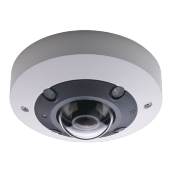
Introduction OVERVIEW The OE-C9112F12 outdoor 12MP IP fisheye camera is equipped with a 1.65mm fixed lens for 360° single- camera coverage in ultra high-definition. True WDR, true day/night, and adaptive IR technology ensure the OE-C9112F12 provides only exceptional image quality in diverse lighting environments. Adaptive IR technology enhances low-light image performance by adjusting IR output to prevent overexposure of objects as they move closer to the camera. -
Page 8: Getting Started
BOX CONTENTS Before proceeding, please confirm that the box contains the items listed here. Please contact your dealer for assistance if any item is missing or has defects. OE-C9112F12 Fisheye Camera Self-tapping screws/M4/6.8MM (x3) & and Plastic Anchors 4-5MM (x 3) -
Page 9: Camera Overview
CAMERA OVERVIEW CAMERA DIMENSIONS CONNECTIONS RJ-45 For connector and PoE connections Pink Audio In (Line In) Audio I/O Green Audio Out (Line Out) Black DC 12V - Power (12vDC)* DC 12V + Alarm In - Alarm In + Alarm I/O Alarm Out - Alarm Out + *12vDC power input port should be plugged when not in use. -
Page 10: Power Connection
Note OpenEye recommends against using more than one power source at a time. Do not use a PoE power source when providing the camera with 12vDC power. If using Power over Ethernet (PoE), make sure Power Sourcing Equipment (PSE) is in use in the network. -
Page 11: Network Camera Manager
Network Camera Manager OpenEye Network Camera Manager (NCM) is a software tool that allows you to quickly and easily connect and configure your OpenEye IP Cameras. This software allows you to apply the camera password, assign IP addresses, configure video settings, and update firmware on multiple cameras at once. -
Page 12: Username And Password
Username: admin The admin user password can be set using the following methods: 1. OpenEye recorders running Apex 2.6 or newer will automatically set a new unique password when added in setup, if a new password has not already been set. -
Page 13: Live View
Live View The camera displays a live view using the MJPEG stream for setup purposes. Setup – Go to the Setup tab to access the camera menus Advanced – Go to the Advanced tab to configure advanced camera features Logout – Log out the current user Languages –... -
Page 14: Setup
SETUP The Setup menu allows for quick camera configuration. The same tabs can be found in the Advanced menus. Follow the links below for full descriptions of Setup and Settings options: SYSTEM SETTING Camera Name User Setup IP Address PICTURE SETUP Camera Tab Motion Detection STREAMING SETTING... -
Page 15: Advanced
ADVANCED SYSTEM SETTING Camera Setup The Camera Setup tab displays the product model, time zone, daylight saving time option, date format, and the option to sync camera time with a computer, NTP server, or manually enter a time. Host Name - The Host Name is for camera identification. If the alarm function is enabled and is set to send alarm messages by Mail / FTP, the name entered here will be displayed in the alarm message. - Page 16 Time format - Choose a time format (yyyy/mm/dd or dd/mm/yyyy) from the drop-down menu. The format of the date and time displayed above the live video window will be changed according to the selected format. Sync with Computer Time - Video date and time display will synchronize with the PC’s time. Manual - The administrator can set video date and time manually.
-
Page 17: User Setup
User Setup The User Setup tab allows you to set an admin password, add users and permissions, set authentication type and enable a lockout function for login attempts. Admin Password – This allows the administrator to reset the password. Enter the new password in Admin password and Confirm password. - Page 18 Manage User Delete user - Pull down the User name drop-down menu and select the username to be deleted. • Click on Delete to remove the selected name. Edit user - Pull down the User name drop-down menu and select the username. Click on Edit and •...
-
Page 19: Ip Address
IP Address The IP Address tab allows you to configure the connected camera network settings. General – These settings are for configuring a new IP address for the camera. Get IP address automatically (DHCP) - Select Get IP address automatically and click Save to •... - Page 20 Advanced – Advanced is for configuring the camera’s Web Server port, RTSP port, MJPEG over HTTP port, and HTTPS port: Web Server port - The default web server port is 80. With the default web server port 80, users • can input the IP address of the camera in the URL bar of a web browser to connect the camera.
- Page 21 DDNS - Dynamic Domain Name System (DDNS) allows a host name to be constantly synchronized with a dynamic IP address. In other words, it allows those using a dynamic IP address to be associated to a static domain name so others can connect to it by name. Enable DDNS - Check to enable DDNS.
-
Page 22: Network Advanced
Network Advanced Qos - QoS allows differentiated service levels for different types of traffic packets, which guarantees delivery of priority services especially when network congestion occurs. Adapting the Differentiated Services (DiffServ) model, traffic flows are classified and marked with DSCP (DiffServ Codepoint) values, and thus receive the corresponding forwarding treatment from DiffServ capable routers. - Page 23 SNMP Settings - With Simple Network Management Protocol (SNMP) support, the camera can be monitored and managed remotely by the network management system. SNMP v1 / v2 Enable SNMP v1 / v2 - Select the version of SNMP by checking the box. •...
- Page 24 Authentication Type - There are two authentication types available: MD5 and SHA. Select SHA for • a higher security level. Authentication Password - The authentication password must be 8 characters or more. The input • characters / numbers will be displayed as dots for security purposes. Note The valid characters are A-Z, a-z, 0-9 and !#$%&’-.@^_~.
-
Page 25: Network Security
Network Security HTTPS - HTTPS allows secure connections between the camera and the web browser using Secure Socket Layer (SSL) or Transport Layer Security (TLS), which ensure camera settings and secure Username / Password. HTTPS requires installing a self-signed certificate or a CA-signed certificate. To use HTTPS on the camera, an HTTPS certificate must be installed. - Page 26 Enable HTTPS - Check the box to enable an HTTPS secure connection. Once enabled, choose one from the following two secure modes. HTTP & HTTPS - Under this mode, HTTP & HTTPS secure connections are enabled. • HTTPS only - Under this mode, the secure connection is ensured by HTTPS only. •...
-
Page 27: Alarm Application
Alarm Application The camera supports one alarm input and one relay output to catch event images. Alarm Switch - The default setting for the Alarm Switch function is Off. Enable the function by selecting On. Users can also activate the function according to the schedule previously set in the Schedule setting page. - Page 28 Upload Image by FTP - The administrator can assign an FTP site and configure various • parameters. When the alarm is triggered, event images will be uploaded to the appointed FTP site. Note One of the streams must be set as MJPEG; otherwise this function cannot be accessed. Pre-trigger buffer - Allows users to check what caused the trigger.
- Page 29 Send HTTP Notification - Check to select the destination HTTP address. Specify the parameters • for event notifications by Alarm triggered. When an alarm is triggered, the HTTP notification will be sent to the specified HTTP server. Record Video Clip - Check to select a video recording storage type, SD Card or NAS (Network- •...
-
Page 30: Tampering And Network Failure Detection
Tampering and Network Failure Detection The Tampering Alarm function helps the IP camera against tampering, such as deliberate redirection, blocking, paint spray, or a covered lens, etc., through video analysis and reaction to such events by sending out notifications or uploading snapshots to the specified destinations. Detection of camera tampering is achieved by measuring the differences between the older frames of video (which are stored in buffers) and more recent frames. - Page 31 Tampering Duration - Minimum Tampering Duration is the time for video analysis to determine whether camera tampering has occurred. Minimum Duration could also be interpreted as defining the Tampering threshold; a longer duration represents a higher threshold. The Tampering Duration time range is from 10 to 3600 sec.
- Page 32 Continue image upload - Upload the triggered images during a certain time or keep uploading until the trigger is off. Upload for __ sec - Enter the duration in the field. Images will be uploaded to the E-mail for the duration when tampering is triggered. The setting range is from 1 to 99999 sec. Upload during the trigger is active - Continually upload to E-mail until tampering stops.
-
Page 33: Network Failure Detection
Network Failure Detection Allows the camera to ping another IP device within the network periodically and generates some actions in case a network failure occurs. Being capable of implementing local recording (through a microSD/SD card) or remote recording (via NAS) when network failure happens, the camera can be a backup recording device for the surveillance system. -
Page 34: Mail, Http And Ftp Setup
Mail, HTTP and FTP Setup... - Page 35 Mail - The administrator can send an E-mail via Simple Mail Transfer Protocol (SMTP) when an alarm is triggered. Two sets of SMTP can be configured. Each set includes SMTP Server, Account Name, Password and E- mail Address settings. Click on Save when finished. Then, please click on Test to check the connection between the camera and the specified SMTP (mail) server.
-
Page 36: Sd Card
SD Card Users can implement local recording to the microSD/SDHC/SDXC card up to 512GB. This page shows the capacity information of the microSD/SD card and a recording list with all the recording files saved on the memory card. Users can also format the microSD/SD card and implement automatic recording cleanup through the setting page. - Page 37 Device Information - After the microSD/SD card is inserted into the camera, the card information such as memory capacity and status will be shown at Device Information. Recording Source - Select a video stream to set as the recording source. The default format of the video stream is Stream 1.
-
Page 38: Network Share
Network Share Users can store the recording videos to a network share folder, or NAS (Network-Attached Storage). A NAS device is used for data storage and data sharing via network. This page displays the capacity information of the network device and a recording list with all the recording files saved on the network device. - Page 39 Device Information - When a NAS is successfully installed, the device information such as the memory capacity and status will be shown at Device Information. Storage Settings - The administrator can set the camera to send the alarm messages to a specific NAS site when an alarm is triggered.
-
Page 40: Recording Schedule
Recording Schedule In Recording, users can specify the recording schedule that fits the present surveillance requirement. - Page 41 Recording Storage - Select a recording storage type, SD Card or Network Share. Enable Recording Schedule - Two types of schedule mode are offered: Always and Only during time frame. Users can select Always to activate microSD/SD card or Network Share Recording all the time. Or, set a schedule on the time frame.
- Page 42 Pre-trigger buffer – Defines how many images are uploaded before the triggered moment. Post-trigger buffer - Defines how many images are uploaded after the triggered moment. Note The Pre-trigger buffer generally ranges from 1 to 20 frames. Upload Image to SD Card – Check for images to be uploaded to the SD Card periodically. •...
-
Page 43: Maintenance
Maintenance Users can export configuration files to a specified location and retrieve data by uploading the configuration file to the camera. Export Files - Users can save the system settings by exporting a configuration file (.bin) to a specified location for future use. Click on Export, and the popup File Download window will come out. Click on Save and specify a desired location for saving the configuration file. -
Page 44: Software
Software The current software version is displayed on the software version page. To upgrade the camera software: 1. Click on Browse and locate the upgrade file. 2. Pick a file type from the drop-down menu. 3. Click on Upgrade. -
Page 45: Log File
Log File The camera keeps a record of the system’s behavior and information related to the camera. This log data can be exported for future use. Click generate syslog and the Save File As dialog window will pop up. Select the file destination and click Save to export the log data. 37792AB... -
Page 46: Picture Setting
PICTURE SETTING Camera Setup You can adjust the camera image settings under Camera Setup. Exposure Exposure is the amount of light received by the image sensor. It is determined by the width of lens diaphragm opening, the shutter speed and other exposure parameters. Night Mode Priority - Choose between Normal or High Light Detail Max Gain - Maximum Gain can be set to reduce image noises. - Page 47 White Balance A camera needs to find reference color temperature, which is a way of measuring the quality of a light source, for calculating all the other colors. Users can select one of the White Balance Control modes according to the operating environment. Auto - The Auto mode is suitable for environments with light source having color temperature in the range roughly from 2700K to 7800K.
- Page 48 Picture Adjustment Brightness - The brightness level of the images is adjustable from -12 to +13. The default value is 0. Sharpness - The sharpness level of the images is adjustable from +0 to +15. The edge of the objects is enhanced as the sharpness level increases.
- Page 49 IR Function Day/Night Function - Define the action of the IR cut filter and IR LED lights. Refer to the descriptions of each option below to select a suitable mode: Auto Mode - With this mode, the camera can decide the occasion to remove the IR cut filter. •...
- Page 50 Noise Reduction The camera provides multiple Noise Reduction options for delivering optimized image quality especially in extra low-light conditions. 3DNR - 3DNR (3D Noise Reduction) function delivers optimized image quality especially in extra low-light conditions. Different levels of 3DNR are provided, including 3DNR Low, 3DNR Mid and 3DNR High. Higher level of 3DNR generates relatively enhanced noise reduction.
-
Page 51: Motion Detection
Profile Camera Profile allows users to setup the desired image parameters for specific environments with different time schedules. Users can setup at most 10 sets of camera parameter configuration under the Camera tab. To enable this function, users must setup the schedules in advance. Refer to the Schedule section for further details on schedule setup. - Page 52 The function supports up to four sets of Motion Detection Settings. Settings can be chosen from the Motion Detection drop-down menu. Motion Indication Bar - When the Motion Detection function is activated and motion is detected, the signals will be displayed on the motion indication bar. The motion indication bar will display green or red when there is any motion occurrence in the detection region.
- Page 53 Motion Detection - By default, the Motion Detection function for each Motion Detection Setting is Off. Select On to enable Motion Detection. Users can also activate the function according to the schedule previously set in the Schedule setting page. Select By schedule and click Please select… to choose the desired schedule from the drop-down menu.
- Page 54 Send Alarm Message by FTP/E-Mail - The administrator can select whether to send an alarm • message by FTP and/or E-mail when motion is detected. Upload Image by FTP - The administrator can assign an FTP site and configure various •...
- Page 55 duration after motion is triggered. The setting range is from 1 to 99999 sec. Select Upload during the trigger active to record the triggered video until the trigger is off. File Name – Enter a file name in the field. The file name format of the uploaded image can be •...
-
Page 56: Video Mask
Video Mask Active Mask Function • Add a Mask - Check an Enable to display Mask checkbox, and a red frame will display in the Live Video pane. Drag and drop to adjust the mask’s size and place it on the target zone. Five video masks can be set. -
Page 57: Fisheye Setting
Fisheye Setting Fisheye Dewarping Type - Choose a method to dewarp the fisheye source images. The options are Front End Camera Dewarping and Back End Software Dewarping. After a dewarping type is selected, click Save. Front End Camera Dewarping - Front End Camera Dewarping is a dewarping method that •... -
Page 58: Text Overlay
Text Overlay Display data including date & time / text string / subtitle / image on the live video pane. Overlay Type - Users can select at most three items out of four options including date & time / text string / subtitle / image to display on the live video pane. - Page 59 Include Image - Check the box to enable image display on the Live Video Pane and a Video • Text Overlay Window will show up. Click and drag the image to the preferred display position, and then decide the string align position (left / right). Click on Set to confirm the settings.
-
Page 60: Streaming Setting
STREAMING SETTING Video Resolution Encoding - Select Yes from the drop-down menu to enable Stream 2~Stream 4 encoding. Or select No to disable the streaming encoding. Encode Type - The available video resolution formats include H.265, H.264, and MJPEG. Users can select the preferred encode type from the drop-down menu. - Page 61 VBR - Video bitrate varies according to the activity of the monitoring environment to achieve • better image quality. LBR - LBR keeps low bitrate and ensures superior image quality. To implement LBR control, • setup the compression level and dynamic GOV for each streaming accordingly beforehand. Compression - Based on the current application area and streaming bitrate, select the most suitable compression level: high, mid, or low.
-
Page 62: Video Rotation
Video Rotation Rotate Function - Users can change video display type if necessary. Selectable video rotate types include Mirror video and 90/180/270 degree clockwise rotate. Refer to the following descriptions for the different video rotate type. Mirror - Select yes from the drop-down menu, and the image will be rotated horizontally. •... -
Page 63: Web Viewer
Web Viewer With the Video OCX protocol setting, the administrator can select RTP over UDP, RTP over RTSP(TCP), RTSP over HTTP or MJPEG over HTTP, for streaming media over the network. In the case of multicast networking, users can select the Multicast mode. Click on Save to confirm the setting. Video OCX protocol setting options include: RTP over UDP / RTP over RTSP(TCP) / RTSP over HTTP / MJPEG over HTTP •... -
Page 64: Audio
Audio The administrator can adjust the sound Transmission Mode, the Server Gain Setting and the audio Bit Rate. Setting for enabling sound recording to the microSD/SD card is also available. Transmission Mode • Full-duplex (Talk and Listen simultaneously) - In Full-duplex mode, the local and remote sites can communicate with each other simultaneously. - Page 65 Bit Rate - Selectable audio transmission bit rate includes 16 kbps, 24 kbps, 32 kbps, 40 kbps, uLAW (64 kbps), ALAW (64 kbps), AAC (128 kbps), PCM (128 kbps), PCM (256 kbps), PCM (384 kbps), and PCM (768 kbps). Higher bit rates will allow for higher audio quality and require a bigger bandwidth. Click Save to confirm the settings.
- Page 66 All rights reserved. No part of this publication may be reproduced by any means without written permission from OpenEye. The information in this publication is believed to be accurate in all respects. However, OpenEye cannot assume responsibility for any consequences resulting from the use thereof.
Need help?
Do you have a question about the OE-C9112F12 and is the answer not in the manual?
Questions and answers