Table of Contents
Advertisement
Quick Links
Advertisement
Table of Contents

Related Manuals for NEC Promise SuperTrak EX8350


Summary of Contents for NEC Promise SuperTrak EX8350
- Page 1 Promise SuperTrak EX8350 Express 5800 120Lh Additional DAC Battery User’s Guide...
- Page 2 This page is deliberately left empty.
- Page 3 The information disclosed in this document, including all designs and related materials, is the valuable property of NEC Computers S.A.S. and/or its licensors. NEC Computers S.A.S. and/ or its licensors, as appropriate, reserve all patent, copyright and other proprietary rights to this document, including all design, manufacturing, reproduction, use, and sales rights thereto, except to the extent said rights are expressly granted to others.
- Page 4 This page is deliberately left empty.
-
Page 5: Preface
For the Promise SuperTrak EX8350 Disk Array Controller (SATA2) to which the BBU is connected, refer to the User’s Guide coming with the disk array controller. - Page 6 Keep this User's Guide at hand for quick reference at anytime necessary. Be sure to read this section carefully. NOTES ON USE - Always read the Notes - The following includes information necessary for proper and safe operation of the product. SAFETY INDICATIONS In the User’s Guide, "WARNING"...
-
Page 7: Symbols Used In This Manual And Warning Labels
Symbols Used in This Manual and Warning Labels Attentions Indicates a general notice or warning that cannot be specifically identified. Indicates that improper use may cause an electric shock. Indicates that improper use may cause personal injury. Indicates that improper use may cause fumes or fire. Prohibited Actions Indicates a general prohibited action that cannot be specifically identified. -
Page 8: Safety Indications
NEC does not assume any liability for accidents resulting in injury or death, or for any damages to property that may occur as a result of using the product in such facilities, equipment, or control systems. - Page 9 Power Supply and Power Cord Use CAUTION Disconnect the power cord(s) before installing or removing the product in/from the server. Make sure to power off the server and disconnect the power cord(s) from a power outlet before installing/removing the product in/from the server, or connecting with the peripheral devices. All voltage is removed only when the power cords are unplugged.
- Page 10 Do not use any unauthorized interface cable. Use only interface cables authorized by NEC and locate a proper device and connector before connecting a cable. Using an unauthorized cable or connecting a cable to an improper destination may cause a short circuit, resulting in a fire.
- Page 11 Cleaning and Working wit h the Product WARNING Do not disassemble, repair, or alter the server. Never attempt to disassemble, repair, or alter the product on any occasion. Failure to follow this instruction may cause an electric shock or fire as well as malfunctions of the product.
- Page 12 viii During Operation CAUTION Avoid contact with the server during thunderstorms. Disconnect the power plug from the outlet when a thunderstorm is approaching. If it starts thundering before you disconnect the power plug, do not touch any part of the server containing the product. Failure to follow this warning may cause an electric shock.
-
Page 13: Warning Labels
Warning Labels The warning label is attached to the product with possible danger or their vicinity in your product to inform the user that a hazardous situation may arise when operating the product. (Do not intentionally remove or damage any of the labels.) If you find any labels totally/partially removed or illegible due to damage, contact your sales representative. -
Page 14: Notes On Use For Correct Operation Of Bbu
Notes on Use for correct operation of BBU - Note the following when you use the BBU. If you ignore the notes, your assets (including important data and/or other devices) may be damaged. The BBU is an additional battery exclusively used for the Promise SuperTrack EX8350 Disk Array Controller (SATA2). -
Page 15: Transfer To Third Party
For details on data erasure, ask your sales representative. NEC assumes no liability for data leakage if the product is transferred to third party without erasing the data. -
Page 16: Table Of Contents
Contents Preface.................................... i NOTES ON USE - Always read the Notes - ........................ii Symbols Used in This Manual and Warning Labels....................iii Safety Indications ..............................iv Warning Labels ................................ix Notes on Use for correct operation of BBU -......................x This Manual ................................x In the Package................................ -
Page 17: Chapter 1 - Overview
Chapter 1 - Overview First read this chapter if you use the Additional DAC Battery (called BBU hereafter) for the first time. This chapter describes the characteristics and configuration of the BBU and outlines the additional battery installation job. 1. Characteristics of BBU The BBU is an additional battery exclusively used for the Promise SuperTrack EX8350 Disk Array Controller (SATA2) (called disk array controller hereafter). -
Page 18: Installation Flow
3. Installation Flow The following shows the job flow for installing the BBU. For details, see the respective chapters. Start Chapter 1 Check BBU and accessories. Describes how to check the BBU and Check notes on installation. accessories in the package and the notes on installation. -
Page 19: Names And Functions Of Sections
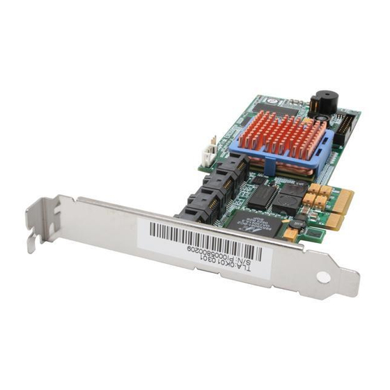
5. Names and Functions of Sections This section describes the sections of the BBU. Front view Battery case Contains lithium ion battery pack. Battery cable Used to connect the BBU to the disk array controller. Full-height PCI bracket Used to fix the BBU to a PCI slot (PCI/PCI-X slot or PCI-Express slot) of the server. To install the BBU to a low-profile PCI slot, replace the bracket with the low-profile PCI bracket coming with the BBU. - Page 20 Rear view Accessories Set up Date Recycle label The label is put on the BBU. It indicates the recycle mark, battery type, and warning, and is filled with the management revision of the BBU. NOTE: The recycle label is also put on the battery pack in the battery case. The label on the battery pack is filled with the management revision of the battery pack.
-
Page 21: Notes
6. Notes Read the following notes thoroughly before using the BBU. 6-1. Notes on Installation Do not put the BBU on a metallic plate including the chassis of the server. Do not hold the BBU with wet hands. If you do not follow these directions, the battery may be short-circuited. To install the BBU in the server, a single PCI slot of the server must be used. -
Page 22: Chapter 2 - Installing Bbu
Chapter 2 - Installing BBU This chapter describes the installation of the BBU in the server. 1. Installation Procedure Install the BBU in the disk array controller in the following procedure. Before starting the installation job, refer to the User’s Guide of the disk array controller and that of the server. -
Page 23: Putting Battery Label
Fix the low-profile PCI bracket to the BBU with the screws (2) removed in step 1. Full-height PCI bracket Low-profile PCI bracket 1-3. Putting Battery Label Fill the date (year and month) when the BBU is installed in the server on the battery label coming with the BBU. -
Page 24: Installing Bbu In Server
1-5. Installing BBU in Server Install the BBU in the disk array controller and the server in the following procedure: Remove the additional slot cover and screw from an unused PCI slot. Remove the cables from the disk array controller. Remove the disk array controller from the server, and connect the battery cable to the battery connector on the disk array controller. -
Page 25: Checking By Utility
2. Checking by Utility After the installation, check the connections and settings of the BBU using the disk array controller management utility "Web-based Promise Array Manager" (called WebPAM hereafter). Boot OS and start WebPAM. Make sure that the Battery icon appears in the Tree View of WebPAM. "Battery"... -
Page 26: Chapter 3 - Operation And Maintenance
Chapter 3 - Operation and Maintenance 1. Maintenance Service Service representatives subordinate to or authorized by us provide services of the BBU with use of genuine parts and high technical capabilities. You can get the services for your own convenience. For the services, contact your sales representatives. - Page 27 Remove the battery pack cable from the battery case connector. Remove the battery pack from the battery case. Battery pack Battery case Replace the battery pack with a new one and install it to the battery case.
- Page 28 New (replaced) battery pack Battery case Connect the battery pack cable to the connector on the battery case. Make sure that the connector pins of the battery pack cable are securely inserted into the battery case connector. New (replaced) battery pack Battery case On the rear face of the BBU, fix the battery pack with the screws (4) removed in step 7.
- Page 29 Fill the replacement date (year and month) on the battery label coming with the battery pack. Then put the label on the PCI bracket. The old label may be either peeled off or left. If left, put the new label on the old one. Fill the year and month.
- Page 30 Connect all the cables to the server and the disk array controller as before. Install the removed side cover and power cords to recover the original state. Turn on the power of the server. After OS is booted, check whether the BBU is recognized correctly. For the checking procedure, see "2.
- Page 31 This page is deliberately left empty.
Need help?
Do you have a question about the Promise SuperTrak EX8350 and is the answer not in the manual?
Questions and answers