Table of Contents
Advertisement
INTEGRATED VOICE EVACUATION SYSTEM
for Mass Notification Installations
Note: Refer to the VX-2000DS Instruction Manual for installation instructions relating to installation of the
VX-2000DS Emergency power supply.
Thank you for purchasing the VM-3000 Series TOA Integrated Voice Evacuation System.
Please carefully follow the instructions in this manual to ensure long, trouble-free use of your equipment.
VOICE ALARM SYSTEM AMPLIFIER
VM EXTENSION AMPLIFIER
REMOTE MICROPHONE
OPERATING INSTRUCTIONS
VM-3000 Series
VM-3240VA
VM-3240E
RM-200M
Advertisement
Table of Contents

Related Manuals for Toa VM-3000 Series


Summary of Contents for Toa VM-3000 Series
- Page 1 Note: Refer to the VX-2000DS Instruction Manual for installation instructions relating to installation of the VX-2000DS Emergency power supply. Thank you for purchasing the VM-3000 Series TOA Integrated Voice Evacuation System. Please carefully follow the instructions in this manual to ensure long, trouble-free use of your equipment.
-
Page 2: Table Of Contents
TABLE OF CONTENTS 1. GENERAL DESCRIPTION ................5 2. FEATURES ......................5 3. SYSTEM CONFIGURATION ................8 4. NOMENCLATURE AND FUNCTIONS 4.1. VM-3240VA Voice Alarm System Amplifier ............. 10 4.2. VM-3240E VM Extension Amplifier ..............10 4.3. RM-200M Remote Microphone ................ 16 5. - Page 3 9.5. Examples 9.5.1. Failure example 1: Communications failure ......... 38 9.5.2. Failure example 2: Short circuit of speaker line 6 ........ 39 9.6. LCD Failure Messages ..................41 10. SETTINGS 10.1. Keys Used for Settings ................... 44 10.2. Setting Hierarchical Chart ................
- Page 4 13.4. General Control Input Terminal Connections 13.4.1. Controlling functions assigned to the General Control Input terminals from the external equipment ........81 13.4.2. Using the local input ................82 13.4.3. Example of connection to external equipment ........83 13.5. Emergency Control Input Terminal Connections ...........
-
Page 5: General Description
1. GENERAL DESCRIPTION The VM-3000 Series Voice Alarm System is an integrated emergency/general announcement broadcast system. The VM-3240VA Voice Alarm System Amplifier plays the central role in the system. Using this amplifier in conjunction with the VM-3240E VM Extension Amplifiers allows larger systems to be built. - Page 6 BGM Volume must be set to lower than 70%. • The FACP and TOA MNS units need to be installed adjacent to each other. • The system is not to be used in buildings providing Suppression Service (Systems using Halon, etc.).
- Page 7 • Use Listed Lowell Manufacturing Rack, Model LER1822, or an equivalent Listed Rack with the following minimum ventilation openings: Fully perforated Front and Back door that has a minimum 90% of the surface area provided with perforated openings. Top Enclosure of the rack shall be provided with a ventilation openings that cover a minimum surface area equal to 40% of the overall top enclosure surface area.
-
Page 8: System Configuration
3. SYSTEM CONFIGURATION • Sample System 1 This example is ideal for installation in facilities and churches does not need the FACP. Notification Appliance Circuit VM-3240VA STATUS OUT EMERGENCY CONTROL IN RM LINK 1 RM-200M DC POWER VX-2000DS DS LINK DC POWER Lead-acid Battery •... - Page 9 • Sample System 2 This example is ideal for installation in large stores applied to the FACP with FACP-Strobe for FACP use only and separate MNS-Strobe for MNS use only. Fire Alarm Control Panel VM-3240VA STATUS OUT EMERGENCY CONTROL IN RM LINK 1 RM LINK 2 RM-200M...
-
Page 10: Nomenclature And Functions
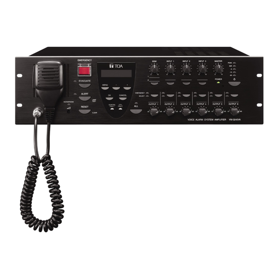
4. NOMENCLATURE AND FUNCTIONS 4.1. VM-3240VA Voice Alarm System Amplifier This amplifier functions as the central unit in the VM-3000 system and its power output is rated at 200 W. Only one unit can be connected in the system. The front panel-mounted LCD displays setting and operation status. The amplifier also features an automatic message function and can play back up to 6 recorded general announcements and 2 recorded emergency announcements. - Page 11 1. Power Switch 7. OK Key [OK] Unit is switched between operating and standby During failure indication: modes each time this switch is pressed. Power is Stops the buzzer when a failure is detected by always supplied regardless of the switch setting. the surveillance function (functioning as a failure acknowledgment key).* 2.
- Page 12 18. Level Meter displayed on the LCD (11). (When there are multiple failures, they can be checked by moving Indicates the output level of the unit’s internal amplifier. the screen using the [+] key (10) or [–] key (8). Failures are not displayed on the LCD when in 19.
- Page 13 [Rear] VM-3240VA 40 41 51 52 53 54 55 VM-3240E 35 36 44 45 51 52 53 54 55 Common to both Voice Alarm System and Extension amplifiers. Differing between Voice Alarm System and Extension amplifiers. Not used. For both emergency and no-emergency use. For no-emergency use only.
- Page 14 39. 24 V DC Input Terminals [VX-2000DS ONLY, 45. DS Link Connector [DS LINK] 24 V POWER IN] Connects to the VX-2000DS Emergency Power Connect power from the VX-2000DS Emergency Supply’s DS-SF link connector. Power Supply Unit. 46. Not used. 40.
- Page 15 55. Control Input Terminals 1 – 8 [CTRL IN 1 – 8, G] DIP Switch 8 [CONFIG] Not used. Control input terminals for general broadcasts. Default setting: ON Functions assigned to each contact input are determined by software settings. (For details, 64.
-
Page 16: Rm-200M Remote Microphone
4.3. RM-200M Remote Microphone The RM-200M Remote Microphone connects to the VM-3240VA for the purpose of making general broadcast announcements. It communicates with the VM-3240VA through its RS-485 interface. Zone selection or automatic announcement start can be assigned to the function key using the dedicated software. No emergency broadcasts can be made with this microphone. - Page 17 1. Indication Label Holder 10. Not used. Write the name, purpose, etc. of the indicator and key on a label and insert the label into the holder from the 11. Microphone top. Labels can be printed using the setting software. Used for making announcements.
-
Page 18: Making General Broadcasts
5. MAKING GENERAL BROADCASTS 5.1. Making Broadcasts from the VM-3240VA 5.1.1. BGM broadcasts Broadcast musical programs from the BGM sound source connected to BGM input terminals 1 or 2 located on the rear panel of the VM-3240VA. Adjust the BGM volume control and the volume control of the designated speakers to an appropriate sound level in advance. -
Page 19: Microphone Announcements
5.1.2. Microphone announcements Make voice broadcasts using the microphone connected to any of audio input terminals 1 – 4 located on the rear panel of the VM-3240VA. Perform input sensitivity settings (Line/Mic selection) while viewing the LCD. (Refer to " Input 1 – 3 Settings" on page 66.) Also, adjust the volume control for the input the microphone is connected to (Inputs 1 –... - Page 20 [Making microphone announcements by activating control inputs] Perform the following settings in advance using the setting software: • Set the priority level of the audio input terminal to which the microphone is connected to any of "1" – "6". (Refer to "General Broadcast Priorities"...
-
Page 21: Broadcasting From The Rm-200M
5.2. Broadcasting from the RM-200M 5.2.1. Microphone announcements Use the RM-200M’s microphone to make announcements. Perform the following settings in advance using the setting software: Assign a broadcast zone selection function to the key. (Refer to "RM Function Key Settings" in "Event Settings" in the separate software instruction manual.) Step 1. -
Page 22: Automatic Announcement Broadcasts
5.2.2. Automatic announcement broadcasts This function makes general broadcasts by activating and playing back automatic announcements recorded and stored in the VM-3240VA. Perform the following settings in advance using the setting software: • Assign a broadcast zone selection to the key. (Refer to "RM Function Key Settings"... -
Page 23: Making Automatic Announcements Using Control Signal Inputs
5.3. Making Automatic Announcements Using Control Signal Inputs This function makes general broadcasts by playing back internal automatic announcements activated when the control input terminals located on the rear panel of the VM-3240VA or VM-3240E receive a broadcast control signal. Perform the following settings in advance using the setting software: Make settings so that the automatic general announcement is broadcast over the designated zone(s) when the control input terminals of the VM-3240VA or VM-3240E are activated. -
Page 24: Summary Of General Broadcast Procedures
5.4. Summary of General Broadcast Procedures 5.4.1. Making general broadcasts from the VM-3240VA Normal status BGM broadcast Microphone announcement (by control input) Microphone announcement (by key operation) Connect a BGM device to the BGM Connect the microphone to the audio input terminal. input terminal. -
Page 25: Making Emergency Broadcasts
6. MAKING EMERGENCY BROADCASTS The following method is used for making emergency broadcasts: Press the Emergency Activation switch on the front panel of the VM-3240VA to initiate emergency broadcasts. Note To use the keys shown below, enable their functions on the setting software. (For details, refer to "Emergency Control Input Settings"... -
Page 26: Making Emergency Broadcasts From The Vm-3240Va
6.1. Making Emergency Broadcasts from the VM-3240VA 6.1.1. Microphone announcements Use the emergency microphone located on the front panel of the VM-3240VA. Emergency Activation switch/Emergency indicator LCD screen [VM-3240VA] Emergency Output indicator Output Selector key All-zone Call indicator Emergency Output indicator All-zone Call Selector key microphone Emergency microphone operation indicator... - Page 27 Step 3. Make announcement while pressing the emergency microphone’s Talk key. Talk key During emergency microphone announcements, the Emergency Microphone Operation indicator and Output indicator both light red. At the same time, the "EMERGENCY VA MICROPHONE" indication is displayed on the LCD. E M E R G E N C Y V A M I C R O P H O N E...
-
Page 28: Automatic Emergency Announcement Broadcasts
6.1.2. Automatic emergency announcement broadcasts This function makes emergency broadcasts with the key on the VM-3240VA’s front panel by playing back the Alert or Evacuation tone and message announcements recorded and stored in the VM-3240VA. Emergency Activation switch/Emergency indicator Evacuation LCD screen Announcement indicator... - Page 29 Step 4. To terminate the emergency broadcast, press the Reset key. [VM-3240VA] Reset key...
-
Page 30: Summary Of Emergency Broadcast Procedures
6.2. Summary of Emergency Broadcast Procedures [Making emergency broadcasts from the VM-3240VA] Normal status Microphone announcement Automatic emergency announcement Press the Emergency Activation switch. Press either the All-Zone Call key or Output key to select the output zone. (If the zone is not selected, emergency broadcasts are made over all zones.) To terminate the emergency broadcast, reset the emergency mode using one of the following methods: •... -
Page 31: Priority Settings
7. PRIORITY SETTINGS 7.1. General Broadcast Priorities In general broadcasts, priorities can be set to the VM-3240VA's input source and the VM-3240E's local input source. Following are such priority-assignable inputs or sound sources: INPUT 1 – 4 (audio input), BGM 1 & 2 (BGM input), RM 1 &... -
Page 32: Emergency Broadcast Priorities
7.2. Emergency Broadcast Priorities Priorities for emergency broadcasts are assigned to the following announcements: microphone announcements from VM-3240VA and Alert/Evacuation announcements. (Priorities are fixed.) The lower the number, the higher the priority. Sound Source Priorities (fixed) Not used. VM-3240VA Microphone Announcement Not used. -
Page 33: Surveillance
9. SURVEILLANCE 9.1. What Is the Surveillance Function? The surveillance function continually monitors operating conditions for each piece of equipment in the system, operations between equipment components, connections and communications between equipment components, power supply conditions and other important component parts and points extending from input to output. -
Page 34: Equipment Operation Upon Failure Detection And Recovery Procedure
NOTICE TO USERS, INSTALLERS, AUTHORITIES HAVING JURISDICTION, AND OTHER INVOLVED PARTIES This product incorporates field-programmable software. In order for the product to comply with the requirements in the Standard for Control and Communication Units for Mass Notification Systems, UL 2572 and CAN/ULC-S576, certain programming features or options must be limited to specific values or not used at all as indicated below. -
Page 35: Equipment Operation Upon Failure Detection
9.4.1. Equipment operation upon failure detection [VM-3240VA] Equipment operation upon failure detection The buzzer sounds, the failure indicator flashes yellow and failure information is displayed on the LCD screen. GENERAL FAULT F A U L T Failure indicator > A M P L I F I E R In this event, a failure of the contents shown on the LCD screen has occurred within the system. -
Page 36: Failure Acknowledgment
[RM-200M] Equipment Operation Upon Failure Detection The Communications Failure indicator flashes yellow. Communications Failure indicator A failure has occurred in communications between the RM-200M and the VM-3240VA. The previous status is automatically restored if communications return to normal. 9.4.2. Failure acknowledgment Perform failure acknowledgment at the VM-3240VA or by use of the control input. -
Page 37: Failure Reset Operation
[Acknowledging failures by the control input] Failure acknowledgment can also be performed by using the control inputs of the VM-3240VA and VM-3240E. (Refer to "Event Settings" "General Control Input Settings" in the separate software instruction manual.) VM-3240VA/3240E Control input Failure Failure acknowledgement reset... -
Page 38: Examples
9.5. Examples Procedures for acknowledging and resetting failures are explained here. 9.5.1. Failure example 1: Communications failure Assuming that the RM-200M’s connection is disconnected within the VM-3000 system, when the failure is detected, the equipment operates as follows: VM-3240VA The buzzer sounds, the Failure indicator flashes yellow and failure information is displayed on the LCD screen. -
Page 39: Failure Example 2: Short Circuit Of Speaker Line
9.5.2. Failure example 2: Short circuit of speaker line 6 Assuming that Speaker Line 6 connected to the VM-3240VA is shorted, when the failure is detected, the equipment operates as follows. VM-3240VA The buzzer sounds, the Failure indicator flashes yellow and failure information is displayed on the LCD screen. - Page 40 Step 2. Determine and remedy the cause. If the cause cannot be determined from the VM-3240VA’s on-screen display, connect a PC and load the log data using the setting software. (For log data loading, refer to "Log Display" in the separate software instruction manual.) Step 3.
-
Page 41: Lcd Failure Messages
9.6. LCD Failure Messages If a failure occurs, its information, including the failure point, is displayed on the VM-3240VA’s front panel- mounted LCD screen. In this event, the display alternates between "Failure information" and "BGM status" except in Emergency mode. Pressing the OK key sets the display to "Failure status." The latest information is displayed on the LCD screen. - Page 42 Failure Location: Automatic Emergency Announcement F A U L T Failure detected in the VM-3240VA’s internal automatic > emergency announcement device. E M E R G E N C Y Failure Location: VM Extension Amplifier (VM-3240E) F A U L T The VM-3240E has overheated or its fuse has blown.
- Page 43 Failure Location: Speaker Line (Ground Fault) F A U L T G r o u n d f a u l t c a u s e d i n a s p e a k e r c o n n e c t e d t o t h e <...
-
Page 44: Settings
10. SETTINGS Perform settings using the VM-3240VA’s LCD screen. To set, select the desired item after entering the setting mode, then advance to the corresponding screen. Even if the setting menu screen is selected by pressing the Menu key during normal operating status, current broadcasts are not interrupted. -
Page 45: Setting Hierarchical Chart
10.2. Setting Hierarchical Chart N o r m a l u s e s t a t u s INPUT 3 MENU LINE/MIC selection (p. 67) BGM selection (p. 69) Setting menu screen Cofiguration Setting screen Password settings (p. 48) I N P U T S E L E C T B G M... -
Page 46: Configuration Settings
10.3. Configuration Settings 10.3.1. Configuration settings hierarchical chart If a password has been set, the password input screen is displayed before entering the Configuration Setting screen. No r ma l s ta tus Password entry (page 47) P A S S W O R D ? CANCEL MENU Setting menu screen... -
Page 47: Password Entry
10.3.2. Password entry If a password has been set, the password entry screen is displayed before entering the Configuration Setting screen. (For password settings, refer to page 48.) Step 1. When a password has been set, pressing the OK Setting menu screen key on the setting menu screen displays the S E L E C T M E N U... -
Page 48: Configuration Setting Items
10.3.3. Configuration setting items The screens shown here are only examples and may differ from the actual displays. The sections in are the setting items or contents that vary with the operation of the [+] or [–] key. [Password settings] Passwords must be set. - Page 49 [Date/time settings] Set the date and time. Default setting: "2008 JAN 01, 00:00" Date/time settings Step 1. Press the OK key on the Clock Setting screen. The setting screen for date and time is displayed. 2 : C L O C K S E T T I N G Note Pressing the Cancel key returns the display to the original...
- Page 50 [Network settings] Set the IP address and subnet mask. Network settings 3 : N E T W O R K S E T T I N G 1, 7 MENU IP address settings Subnet mask settings 3 1 : I P 3 2 : S U B N E T A D D R E S S M A S K...
- Page 51 Step 5. Press the OK key when the underline is at the rightmost digit to register the IP address. Step 6. Press the Cancel key after setting is complete. The display reverts to the Network Settings screen. <Subnet mask settings> Step 7.
- Page 52 [Log transmission] Transmit logs from the VM-3240VA to a PC. Log transmission Step 1. Press the OK key on the Log Transmission screen. 4 : L O G D A T A The indication "TRANSMITTING" is displayed on the screen. V M –...
- Page 53 [Transmission of PC-set data] Transmit data set by a PC to the VM-3240VA from the PC or conversely from the VM-3240VA to the PC. Set data transmission Step 1. Press the OK key on the Set Data 5 : S E T T I N G D A T A Transmission screen.
- Page 54 Transmission in Transmission in progress progress R E C E I V I N G T R A N S M I T T I N G Step 5. Press the OK key. C O M P L E T E C O M P L E T E The display reverts to the source and destination selection screen.
- Page 55 [Transmission of EV sound source data] Transmit EV sound source data from a PC to the VM-3240VA or conversely from the VM-3240VA to the PC. EV sound source data transmission Step 1. Press the OK key on the EV sound 6 : E V D A T A source transmission screen.
- Page 56 The EV message sound source file registration screen is displayed. Press the [PC->VM-3000VA] button to transmit sound source data from the PC to the VM-3240VA after reading the sound source data into the above screen. Press the [VM-3000VA->PC] button to transmit sound source data from the VM-3240VA to the PC.
- Page 57 [Emergency broadcast setting] Set the Emergency broadcast function following the procedure below. Step 1. Press the OK key on the Emergency broadcast setting screen. The setting screen for the Emergency broadcast function is displayed. Emergency broadcast setting Note 7 : E M G B R O A D C A S T Pressing the cancel key returns the display to the original S E T T I N G...
-
Page 58: Information Settings
10.4. Information Settings 10.4.1. Information setting hierarchical chart N o r m a l s t a t u s CANCEL MENU Information setting screen Setting menu screen Usage language selection S E L E C T M E N U I N F O R M A T I O N S E L E C T L A N G U A G E... - Page 59 [Version information display] Version information is displayed on the VM-3240VA's front panel-mounted LCD screen. Indicates the model number in short form. VA: VM-3240VA having a LCD screen E1: VM-3240E connected to the VM-3240VA V E R S I The number represents the unit ID number. Indicates the version number of the equipment shown above.
-
Page 60: Audio Settings
10.5. Audio Settings This function is used to adjust the audio setting parameters. Tone settings can be adjusted for Input 4 and volume adjusted for BGM 1 and 2 as well as for the chime interlocked with the microphone, Alert/Evacuation message announcements, and automatic general announcements. -
Page 61: Audio Setting Items
10.5.2. Audio setting items The screens shown here are only examples and may differ from the actual displays. The sections in are the setting items or contents that vary with the operation of the [+] or [–] key. [Input 4 tone settings] Set the tone (bass and treble) for Input 4. - Page 62 [BGM 1 and BGM 2 volume adjustment] Adjust the volume of BGM1 and BGM2. Setting range +10 dB to –10 dB (default: 00) (Example. When adjusting BGM 1 volume:) Step 1. Using the [+] and [–] keys, adjust the volume on the BGM 1 or BGM 2 Volume Settings screen.
- Page 63 [Evacuation message announcement volume adjustment] Adjust the volume of Evacuation message announcement internally pre-recorded on the VM-3240VA. Setting range +10 dB to –10 dB (default: 00) Evacuation message announcement volume adjustment E V A C U A T E V O L U M E Step 1.
- Page 64 [Automatic general message announcement volume control] Adjust the volume of Automatic general message announcements (EV1 – 6). Setting range +10 dB to –10 dB (Default: 00) EV1 - 6 represent the Automatic general message announcement numbers. For details, refer to the separate software instruction manual.
-
Page 65: Surveillance Settings
10.6. Surveillance Settings Notes • When using the Surveillance function (refer to "What Is the Surveillance Function?" on page 33), be sure to perform this setting after system installation and connections have been completed. Also, be sure to perform this setting when the number of connected speakers has been changed. If this setting is not performed, the surveillance function will not operate correctly. -
Page 66: Inputs 1 - 3 Settings
10.7. Inputs 1 – 3 Settings LINE/MIC input can be selected, phantom power turned ON/OFF, and treble and bass set for Inputs 1 – 3 during actual sound output. Perform this setting after system installation and connections have been completed. The screens shown here are only examples and may differ from the actual displays. -
Page 67: Inputs 1 - 3 Setting Items
10.7.2. Inputs 1 – 3 setting items [LINE/MIC selection settings] Select either LINE or MIC input. Setting range Line and Mic (Default: LINE) [Phantom ON/OFF settings] This setting item will not appear when "LINE" is selected at the LINE/MIC selection setting item. Set whether to enable or disable the phantom power. -
Page 68: Bgm Settings
10.8. BGM Settings Bass and treble of BGM can all be set during actual sound output. Perform this setting after system installation and connections have been completed. The screens shown on the previous page are only examples and may differ from the actual displays. The sections in are the setting items or contents that vary with the operation of the [+] or [–] keys. -
Page 69: Bgm Setting Items
10.8.2. BGM setting items [BGM selection] Select BGM 1 or 2. Press the OK key to confirm the selected BGM output and commence BGM broadcasting. (For details, refer to "BGM Broadcasts" in "Making General Broadcasts" on page 18.) Setting range BGM 1, BGM 2 and OFF (default) [Treble settings] Perform treble settings. -
Page 70: Rm-200M Remote Microphone Settings
11. RM-200M REMOTE MICROPHONE SETTINGS 11.1. DIP Switch Functions DIP switch Switch Function Factory-preset Unit ID No. setting – Talk key operation – Compression ON/OFF RM-200M side 11.2. Unit ID Number Settings (Switches 1 and 2 operation) To set the unit ID number of the RM-200M, use the DIP switches 1 and 2. Make the Setting Software-assigned ID numbers for these units and the ID numbers set by their DIP switches identical. -
Page 71: Installation
12. INSTALLATION 12.1. Installing the RM-200M on a Wall To mount the RM-200M on the wall, the following parts are required. WB-RM200 Wall Mounting Bracket for the RM-210 ....1 (option) Machine screw M3.5 x 20 (for an electrical box mounting) ..2 (supplied with the WB-RM200) Tapping screw 4 x 25 (for direct wall mounting) ...... -
Page 72: Creating Remote Microphone Name Labels
12.2. Creating Remote Microphone Name Labels Using the VM-3000 Setting Software function, assigned names of preset RM-200M Function keys can be printed out. Once printed, cut out the printed names with scissors to use them as corresponding name labels. The paper used for the name label must be under 0.2 mm in thickness. Note For creating and printing name labels using the VM-3000 Setting Software, see the separate Setting Software Instructions, "Labels for Remote Microphones."... -
Page 73: If The Name Label Is Not Printed Correctly
12.2.2. If the name label is not printed correctly The name label created using the VM-3000 Setting Software may not be printed in correct size depending on the configuration environment of your PC. In such cases, try one of the methods described below. (1) Preparation by hand Copy the "Pattern paper for hand writing"... -
Page 74: Pattern Paper For Hand Writing
12.2.4. Pattern paper for hand writing Name label A Name label B Cutting guideline Shown in actual size... - Page 75 Name label B Name label B Name label B Name label B Shown in actual size Cutting guideline...
-
Page 76: Rack Mounting
* 3 U size = 133.5 mm (reference size) • The rack-mounting screws supplied with the units other than the VM amplifiers are dedicated for the TOA racks. Never use them for any other rack. Notes • Because the VM-3240VA, VM-3240E, and VX-2000DS are heavy, use guide rails (separately prepared) in the rack to safely mount and securely support the units. -
Page 77: Connections
13. CONNECTIONS 13.1. Removable Terminal Plug Connection Notes • Do not use a micro screwdriver. Sufficient torque is not given to the screws when tightening them, and connections may not be secured. • Avoid soldering stranded or shielded cable, as contact resistance may increase when the cable is tightened and the solder is crushed, possibly resulting in an excessive rise in joint temperatures. -
Page 78: Audio And Control Connection Example
13.2. Audio and Control Connection Example Paging microphones CD Player BGM sources Cassette Player VM-3240VA rear Talk switch or other make contact VM-3240VA/3240E rear Control Audio Notification Appliance Circuits Extender RM-200M CAT. 5 VM-3240VA/3240E rear RM-200M CAT. 5 RJ45 male connector Audio line RCA plug Control line... - Page 79 [Fire Alarm Control Panel Connection Example] Fire Alarm Control Panel Paging microphones CD Player BGM sources Cassette Player VM-3240VA rear Talk switch or other make contact VM-3240VA/3240E rear Control Audio Notification Appliance Circuits Extender RM-200M CAT. 5 VM-3240VA/3240E rear RM-200M CAT.
-
Page 80: Rm-200M Remote Microphone Connections
13.3. RM-200M Remote Microphone Connections 13.3.1. Power supply from VM-3240VA or VM-3240E Up to 4 RM-200Ms can be used in a system. The VM-3240VA or VM-3240E can supply power to a single RM-200M only. VM-3240VA/3240E RM-200M DC power line This figure shows VM-3240VA. 13.3.2. -
Page 81: General Control Input Terminal Connections
13.4. General Control Input Terminal Connections 13.4.1. Controlling functions assigned to the General Control Input terminals from the external equipment Following are assignable functions to the General Control Input terminals. (For the function assignments, refer to "General control input settings" in "Event Settings" in the separate software instruction manual.) VA-INPUT 1 –... -
Page 82: Using The Local Input
[Setting example] Shown below is a general control input setting screen in the setting software. The figure shows an example when performing a general broadcast by way of the contact activation. Control input No. 1 Sound source VA-INPUT 1 input Broadcast zone Zone 1 13.4.2. -
Page 83: Example Of Connection To External Equipment
13.4.3. Example of connection to external equipment VM-3240VA rear Press-to-talk switch box* E C H (Remote switch) AWG 28 – AWG 22 * Prepare the switch assembly locally at your end. When using a single-core shielded cable, connect the shielded mesh to both E and C terminals. -
Page 84: Emergency Control Input Terminal Connections
13.5. Emergency Control Input Terminal Connections Following are assignable functions to the Emergency Control Input terminals. (For the function assignments, refer to "Emergency control input settings" in "Event settings" in the separate software instruction manual. Evacuation EV broadcast: This function cannot be used. Evacuation EV stop: This function cannot be used. -
Page 85: External Emergency Control Equipment Connection
13.5.1. External emergency control equipment connection VM-3240VA rear Emergency control Emergency control Fire Alarm input terminals 5 and 6 input terminals 1 – 4 CTRL IN 1 COM 1 CTRL IN 2 COM 2 Contact CTRL IN 3 control RJ45 connector Pin No. -
Page 86: Connections To Detect Failures On The Emergency Control Input Lines
13.5.2. Connections to detect failures on the emergency control input lines Two types of control methods are available for the Emergency control input in the VM-3000 system: Contact control input (Emergency control input terminals 1 – 5) and Voltage control input (Emergency control input terminal 6). - Page 87 [Voltage control input terminal (EMERGENCY CONTROL 6)] 24 V DC is kept applied to the COM terminal under normal condition. Reversing this applied voltage polarity resets an emergency broadcast. The surveillance function judges the line normal when 24 V DC is detected at the COM terminal under normal condition and when 24 V DC is detected at the emergency control input terminal 6 under emergency condition.
-
Page 88: Status Output Terminal Connections
13.6. Status Output Terminal Connections These terminals provide control outputs of relay contact type. VM-3240VA rear Control signals (make contact) are output in synchronization with unit operation. Status Output Terminal The RJ45’s pin arrangement and pin functions are shown below. Pin 1 Pin 2 Pin 3... - Page 89 [NAC Extender connection] VM-3240VA rear NAC EXTENDER EMERGENCY STATUS OUT NAC ACTIVE INPUT CTRL IN 1 10 kΩ NAC FAULT OUTPUT COM 1...
- Page 90 [FACP and NAC Extender connection A] For operating system with a Fire Alarm Control Panel and MNS system has higher priority. VM-3240VA rear FACP EMERGENCY STATUS OUT MNS ACTIVE INPUT FAULT STATUS OUT MNS FAULT INPUT CTRL IN 1 10 kΩ FACP FAULT OUTPUT COM 1 FACP ACTIVE OUTPUT...
- Page 91 (A) MNS is Higher Priority FACP with FACP-Strobe for FACP use only + separate MNS-Strobe for MNS use only. (a) When FACP goes into Evacuation mode The fire alarm audible notification starts. MNS stops all general broadcast. MNS-Strobe is not energized. (b) When MNS goes into Emergency Mode (Active) Leave FACP audible notification off.
- Page 92 [FACP and NAC Extender connection B] MNS System has lower Priority. VM-3240VA rear FACP EMERGENCY STATUS OUT MNS ACTIVE INPUT FAULT STATUS OUT MNS FAULT INPUT CTRL IN 1 10 kΩ FACP FAULT OUTPUT COM 1 4.7 kΩ CTRL IN 4 FACP ACTIVE OUTPUT 4.7 kΩ...
- Page 93 (B) MNS is Lower Priority FACP with FACP-Strobe for FACP use only + Separate MNS-Strobe for MNS use only with MNS is Lower Priority. (a) When MNS goes into Emergency Mode. MNS-Strobe is lit. FACP shall visually indicate and log that the MNS is active. (b) When FACP goes into Emergency mode The fire alarm audible notification starts.
- Page 94 [FACP and NAC and UPS connection] VM-3240VA rear FACP EMERGENCY STATUS OUT MNS ACTIVE INPUT FAULT STATUS OUT MNS FAULT INPUT CTRL IN 1 10 kΩ FACP FAULT OUTPUT COM 1 CTRL IN 8 FACP ACTIVE OUTPUT CTRL IN 3 UPS FAULT OUTPUT 10 kΩ...
-
Page 95: Power Amplifier And Speaker Connections
13.7. Power Amplifier and Speaker Connections VM-3240VA/3240E Speaker... -
Page 96: Connections Between Vm Amplifiers
13.8. Connections between VM Amplifiers VM-3240VA Cat. 5 STP Unit ID No. 1 3 4 5 6 VM-3240E Cat. 5 STP Unit ID No. 2 3 4 5 6 VM-3240E RJ45 male connector Notes • When connecting 2 VM-3240E units or more in a system, set the Unit ID with the DIP switch located on each unit’s rear panel. -
Page 97: Connecting Power Supply Equipment
13.9. Connecting Power Supply Equipment (–)(–)(+)(+) From VX-2000DS Note VM-3240VA Remove the short bar attached at the factory. 120 V AC 60 Hz (–)(–)(+)(+) From VX-2000DS VM-3240E 120 V AC 60 Hz DC power DC power input terminals See “Note” below. output terminals VX-2000DS BATTERY POWER IN... - Page 98 [Required number of VX-2000DS units] One VX-2000DS is required every 3 VM amplifiers. Number of VM amplifiers Number of VX-2000DS' Below is an example showing that one VX-2000DS is required in a system including 3 VM amplifiers. VM-3240VA VM LINK VM-3240E VM LINK VX-2000DS...
-
Page 99: Vm-3000 Cable Usage Table
14. VM-3000 CABLE USAGE TABLE This table shows the cables to be used in the VM-3000 and their connection locations. [VM-3240VA] Terminal to Connect Cable Type Equipment to be Connected to Terminal Equipment Equipment Terminal Plug Cable Type Plug Equipment Name Receptacle Receptacle... - Page 100 [VX-2000DS] Terminal to Connect Cable Type Equipment to be Connected to Terminal Equipment Equipment Terminal Plug Cable Type Plug Equipment Name Receptacle Receptacle Name AC IN 3P inlet AC plug Supplied cable AC plug AC OUTLET AC 120 V, 60 Hz VM-3240VA DS-SF LINK RJ45 (female) RJ45 (male)
-
Page 101: Specifications
15. SPECIFICATIONS 15.1. VM-3240VA Voice Alarm System Amplifier Power Source 120 V AC, 60 Hz Power Consumption 690 VA (at rated output), 260 W (according to UL60065), 63 W (at no signal) Rated Output 240 W, 21 Ω (according to UL60065) 200 W, 25 Ω... - Page 102 DS Link Connecting the VX-2000DS, RJ45 female connector Link cable: Category 5 Shielded Twisted-Pair straight cable (CAT5-STP) 0 to 49°C (32 to 120°F) Operating Temperature 5% to 95% RH (no condensation) Operating Humidity Panel: Aluminum, hair-line, black Finish Case: Surface-treated steel plate, black, paint 482 (w) x 132.6 (h) x 431.2 (d) mm (18.98"...
-
Page 103: Vm-3240E Vm Extension Amplifier
15.2. VM-3240E VM Extension Amplifier Power Source 120 V AC, 60 Hz Power Consumption 690 VA (at rated output), 260 W (according to UL60065), 63 W (at no signal) Rated Output 240 W, 21 Ω (according to UL60065) 200 W, 25 Ω (according to UL2572) 200 W, 25 Ω... -
Page 104: Rm-200M Remote Microphone
15.3. RM-200M Remote Microphone Power Source 22 V DC Power input jack: Non-polarity type Usable power input plug: Outer diameter ø5.5 mm, inner diameter ø2.1 mm, length 9.5 mm Current Consumption 100 mA or less Audio Output 0 dB*, 600 Ω, balanced Frequency Response 100 Hz –... - Page 105 URL: http://www.toa.jp/ Part code: 133-02-00146-00 Issued: 201507...
Need help?
Do you have a question about the VM-3000 Series and is the answer not in the manual?
Questions and answers