Toa Venas VM-2120 Cookbook
System management amplifier
Hide thumbs
Also See for Venas VM-2120:
- Installation instructions manual (36 pages) ,
- Instruction manual (60 pages) ,
- Instruction manual (60 pages)
Table of Contents
Advertisement
Advertisement
Table of Contents

Related Manuals for Toa Venas VM-2120


Summary of Contents for Toa Venas VM-2120
- Page 1 Cook Book VM-2000 Series SYSTEM MANAGEMENT AMPLIFIER VM-2120/VM-2240...
-
Page 2: Table Of Contents
INDEX 1. GENERAL DESCRIPTION .......................... 2. FEATURES ..............................3. NOMENCLATURE Nomenclature (VM AMPLIFIER) ....................Nomenclature (SV-200M, EV-200, RM-200M, RM-210) ............4. GENERAL PURPOSE BROADCAST INPUT Input 1 – 3 (Mic/Line) ........................ BGM Input ..........................External Connection Terminal (Telephone Device Input) ............External Connection Terminal (VS-900) .................. -
Page 3: General Description
GENERAL DESCRIPTION General Description The TOA System Management Amplifiers VM-2120 and VM-2240 are expressly designed to fulfill increasing requirements for reliable and efficient communications in mid-size facilities such as office buildings, factories, hospitals, transportation terminals and many other sites. Both amplifiers are multifunctional designs, with the VM-2120 rated at 120W and the VM-2240 at 240W. -
Page 4: Features
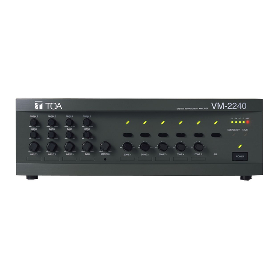
When a VM-2000 Series amplifier is used in combination with an emergency power supply unit*, a backup battery ensures uninterrupted operation during power outages. * TOA DS-1000B or similar emergency power supply unit. During emergency situations a VM-2000 Series amplifier can provide phased emergency broadcasts as per EN60849* standard. - Page 5 NOMENCLATURE Nomenclature (VM Amplifier) System Management Amplifier VM-2120/-2240 [Front] Zone selector key All-zone broadcast indicator Zone indicator Level meter Treble control Failure indicator Bass control Power indicator Name label Input volume control Name label Power switch Zone volume control Emergency indicator Reset key Master volume control All-zone broadcast key...
- Page 6 NOMENCLATURE Nomenclature (EV-200, SV-200M, RM-200M, RM-210) Voice Announcement Board EV-200 Surveillance Board SV-200M Eject button Speaker line impedance setting key CPU status indicator Card access Surveillance input and Voice Announcement Line check key indicator output connector board volume control CF card slot Remote Microphone RM-200M [Right Side] [Top]...
-
Page 7: General Purpose Broadcast Input
GENERAL PURPOSE BROADCAST INPUT Input 1-3 (MIC/LINE) Inputs 1 – 3 can be set for a microphone signal input level ( –60 dB, 600 Ω) or a line signal input level ( –10 dB, 600 Ω) by moving the SETTINGS switch in Fig. 1 to the ON or OFF position. The three inputs also feature Neutrik connectors that permit connection to XLR connectors and phone plugs. - Page 8 GENERAL PURPOSE BROADCAST INPUT BGM Inputs Two background music inputs (BGM INPUTS: RCA pin jack, - 20 dB, 10 kΩ) are provided. An attenuator is also provided for each BGM input to adjust the sound volume when different sound sources are connected. Equipment that can be connected to these input includes: •...
- Page 9 GENERAL PURPOSE BROADCAST INPUT External Connection Terminal (Telephone Device Input) A specified telephone paging number must be preprogrammed into the telephone exchange. The VM amplifier's power can then be switched on remotely by dialing this number from a telephone set, permitting telephone paging to be made from that telephone.
-
Page 10: General Purpose Broadcast Input
GENERAL PURPOSE BROADCAST INPUT External Connection Terminal (VS-900) Use of the VS-900 in conjunction with the VM amplifier permits broadcasts to be made from each station connected to the VS-900. Configure the connections so that two control signals are transmitted from the VS-900 to the VM amplifier's CTRL IN 1 and CTRL IN 2 terminals, then assign different zone groups to the two terminals. - Page 11 GENERAL PURPOSE BROADCAST INPUT Control I/O (Timer) By combining the VM amplifier with a timer, a chime tone can be broadcast at preset times. Pattern 1 No.11 No.16 Program Timer TT-104B Connect the timer (designed to deliver a no-voltage "make" contact output) to Pins 11 and 16 of the VM amplifier's control I/O terminal.
-
Page 12: Voice Announcement Board
GENERAL PURPOSE BROADCAST INPUT Control I/O Connector Functions The rear panel-mounted Control I/O connector enables the VM amplifier to be controlled or monitored by connected external equipment. VM amplifier's D-sub female connector CONTROL I/O Locking nut: 4-40 UNC CONTROL I/O connector pin function table Signal name Signal/logic Function/status... - Page 13 GENERAL PURPOSE BROADCAST REMOTE MICROPHONE Operations and Broadcasting from Remote Microphone Broadcasts from the VM amplifier can be remotely enabled by pressing the keys on the RM-200M or RM-210 Remote Microphone. Remote control is also possible even when two or more Remote Microphones or VM amplifiers are connected.
- Page 14 GENERAL PURPOSE BROADCAST REMOTE MICROPHONE Remote Microphone General Purpose Broadcast (1) Simultaneous All-Zone Broadcast Operation Step 1. Press the ALL-ZONE key. ALL-ZONE The All-zone indicator and all zone indicators (1 – 5) will light. (Press the ALL-ZONE key again to cancel.) (2) Individual Zone Broadcast Operation Step 1.
- Page 15 GENERAL PURPOSE BROADCAST REMOTE MICROPHONE Remote Microphone General Purpose Broadcast (4) Message Broadcast Operation Messages (1 – 5) assigned to broadcast groups require to be programmed into the VM amplifier. Group 1 Zone 1 Message 1 (Selected) Zone 2 Broadcast Zones Zone 3 Group 3...
- Page 16 GENERAL PURPOSE BROADCAST REMOTE MICROPHONE VM Amplifier Connection to the Remote Microphone VM amplifier Connection to the Remote Microphone (Pattern 1) [Operation] All 4 Remote Microphones connected to the VM amplifier can enable the same operation. Two different priority levels can also be assigned to the connected Remote Microphones, depending on application. [Connection] Connect each Remote Microphone in series using the Category 5 STP cable and RJ-45 connectors.
- Page 17 GENERAL PURPOSE BROADCAST REMOTE MICROPHONE Distance between Remote Microphone and VM Amplifier Using the specified cable, connect between the VM amplifier(s) and Remote Microphone(s) via their LINK connectors. They can be connected in any order. (Two connection examples are shown.) Connection example 1 Link cable LINK connector (RJ45)
- Page 18 GENERAL PURPOSE BROADCAST REMOTE MICROPHONE Supplying Power from the VM Amplifier to the Remote Microphone The VM amplifier can only supply power to one Remote Microphone. Therefore, each of the remaining Remote Microphone(s) needs to have a 24 V DC power supply (AC adaptor) of its own. NOTE: When the RM-210 is used to expand the functions of the RM-200M, the power connections remain the same, however cable distances change.
- Page 19 GENERAL PURPOSE BROADCAST REMOTE MICROPHONE Special Power Supply from the VM Amplifier to the Remote Microphone When building a system in which 2 or more Remote Microphones are to be connected to each of two VM amplifiers, a system that eliminates the necessity of an AC adapter for the first RM-200M connected to each VM amplifier can be created by modifying the link cable between the two VM amplifiers.
- Page 20 GENERAL PURPOSE BROADCAST VOICE ANNOUNCEMENT BOARD About the EV-200 The EV-200 digital sound source playback card for automatic broadcast is featured in the VM-2000 Series lineup. Using the optional card, emergency messages can be automatically broadcast or a chime tone sounded at preset times when using an external timer.
- Page 21 GENERAL PURPOSE BROADCAST VOICE ANNOUNCEMENT BOARD Message Activation Messages recorded on the CompactFlash memory card can be played back by activating (no-voltage "make" contact) the control I/O terminal located on the VM amplifier's rear panel, as in the case of the Remote Microphone.
-
Page 22: Voice Announcement Board
GENERAL PURPOSE BROADCAST VOICE ANNOUNCEMENT BOARD Recorded CF Card Messages Messages can be recorded on the CF card using the EV-350R. In the EV-350R, a series of messages is called a "program," which is called a "message" when played back using the EV-200 and VM amplifier. Up to 8 Messages (programs) are available, with Nos. - Page 23 GENERAL PURPOSE BROADCAST VOICE ANNOUNCEMENT BOARD Recording To install the EV-200 Voice Announcement Board in the VM amplifier and play back the message, prerecord the message on the CompactFash memory card using EV-350R. When the CF card is first inserted into the EV-200, a pilot tone is written in the card. When using the EV-350R unit for recording, leave the recording space of more than10 seconds.
-
Page 24: About Priority Broadcasts
GENERAL PURPOSE BROADCAST ABOUT PRIORITY BROADCASTS Broadcast Priorities The VM-2000 Series features both emergency broadcast and general-purpose broadcast modes. Emergency broadcasts have priority over general-purpose broadcasts, and current general-purpose broadcasts are immediately switched over to emergency broadcast mode if an emergency broadcast is made. - Page 25 GENERAL PURPOSE BROADCAST ABOUT PRIORITY BROADCASTS Priority Setting (General-Purpose Broadcasts) Internal DIP switches 1 2 3 4 5 6 7 8 1 2 3 4 5 6 7 8 VM amplifier's front panel For the following inputs, priorities can be set with the DIP switch. INPUT 1 SW2-1 (Priority 1)
-
Page 26: Expansion Functions
GENERAL PURPOSE BROADCAST EXPANSION FUNCTIONS A Maximum System Employing a Single Master Amplifier In the VM amplifier system, the VM-2120 or the VM-2240 can be expanded as a sub-amplifier to increase the number of broadcast zones. Even in this case, the number of input channels and the EV-200's functions remain unchanged. - Page 27 GENERAL PURPOSE BROADCAST EXPANSION FUNCTIONS How to Connect 3 or More VM amplifiers When connecting 3 or more VM amplifiers, the following settings are required: (1) Master-sub relationship. (2) The number of units to be connected to the system (the total number of sub-VM amplifiers and RM units. The master unit is not included). (3) Unit number for each sub-amplifier.
- Page 28 GENERAL PURPOSE BROADCAST EXPANSION FUNCTIONS The Number of Connectable Speakers Up to 5 broadcast zones can be selected with the VM-2120 and VM-2240. The VM-2120's maximum power output is 120 W, while that of the VM-2240 is 240 W. The following two patterns show the system where speakers of a total of 120 W are connected to the VM-2120 or speakers of a total of 240 W are connected to the VM-2420: Pattern 1: All speakers connected to 5 zones.
- Page 29 GENERAL PURPOSE BROADCAST EXPANSION FUNCTIONS Amplifier Expansion The output of the VM amplifier[(120 W in the case of the VM-2120) (240 W in the case of the VM-2240)] can be expanded. [Operation setting] The system can be configured for large system applications by connecting other PA amplifier to the VM amplifier's speaker outputs.
- Page 30 GENERAL PURPOSE BROADCAST EXPANSION FUNCTIONS Operation of the Quasi-Dual-Origination Broadcast System The quasi-dual-origination broadcast is available when the VM amplifier is connected to a BGM amplifier. Background music (BGM) input to the A-1000 BGM amplifier is broadcast over Zones 1 - 5 in Fig. 1. In Fig.
- Page 31 GENERAL PURPOSE BROADCAST EXPANSION FUNCTIONS Quasi-Dual-Origination Broadcast Connection Quasi-dual-origination broadcasts can be performed by the following system. [Connection] Change the connection of the CN-1003 connector on the VM amplifier's RY circuit board from [2P-3P Short] position to the [1P-2P Short] position. Connect the BGM amplifier speaker output to the VM amplifier's External Speaker input.
- Page 32 GENERAL PURPOSE BROADCAST EXPANSION FUNCTIONS External Standby Amplifier Operation A backup system for VM amplifier failure can be created by configuring the following system. [Operation] During a normal broadcast using two VM amplifiers (Fig.1), one of these amplifiers fails (Fig.2). The SV-200M in the failed amplifier sends failure information to the CPU inside the VM.
- Page 33 GENERAL PURPOSE BROADCAST EXPANSION FUNCTIONS Standby Amplifier Connection In case of amplifier failure, they can be backed up by creating the following system. [Connection] Prepare a standby amplifier with the same output rating as that of the VM amplifier. Install the SV-200M in the VM amplifier and connect the PREOUT to the standby amplifier, and the standby amplifier's output to the VM amplifier's EXTERNAL SP input.
- Page 34 GENERAL PURPOSE BROADCAST EXPANSION FUNCTIONS Operation Using Both Standby and Quasi-Dual-Origination Amplifiers The following system enables the same amplifier to provide both standby and quasi-dual-origination broadcast functions. Quasi-dual-origination broadcasts are normally made using both the VP-1120 or VP-1240 amplifier and the VM Series amplifier.
- Page 35 GENERAL PURPOSE BROADCAST EXPANSION FUNCTIONS Connection When Using Both Standby and Quasi-Dual-Origination Amplifiers The following system permits use of both the BGM amplifier for quasi-dual-origination broadcasts and the standby amplifier. Prepare a standby amplifier (here, a VP-1120 or VP-1240) with the same output power rating (wattage) as that of the VM amplifier.
-
Page 36: Other Functions
GENERAL PURPOSE BROADCAST OTHER FUNCTIONS Rack Mounting The VM amplifier can be mounted in a standard EIA rack (3-unit space) with the use of optional MB-36 hardware. EIA 3UNIT Note: The screws and washers as illustrated are VM amplifier all supplied with the MB-36. Plain washer M4 x 16 screw Rack Mounting Bracket MB-36 (optional) - Page 37 GENERAL PURPOSE BROADCAST OTHER FUNCTIONS Headset Microphone The external microphone input jack located on the rear panel of the RM-200M Remote Microphone can be used to connect a condenser microphone with a 3.5 mm mini-jack. [Example] Connection of the WH-4000A headset microphone to the RM-200M Remote Microphone enables operators to work and talk with both hands free.
- Page 38 EMERGENCY BROADCASTS EMERGENCY BROADCASTS About Emergency Broadcasts <TOA's Efforts to Make the VM-2000 Series Amplifiers Conform to European Safety Standards> European Standard EN60849 Paragraph 4.1 (General System Requirements) describes emergency broadcast systems as follows: a) When any alarm is detected, the system shall immediately disable any function not connected with its emergency role (such as paging, music or general prerecorded announcements being broadcast to the loudspeaker zones requiring emergency broadcasts.
- Page 39 EMERGENCY BROADCASTS EMERGENCY BROADCASTS Operation and Connection Examples as an Emergency Broadcast Amplifier The following system uses the VM amplifier as an emergency/general-purpose broadcast amplifier. General- purpose announcements are made using the microphone and BGM is normally broadcast. In the case of emergencies such as a fire: Emergency messages recorded on the CF card are played back to provide an emergency situation alert and evacuation instructions.
- Page 40 EMERGENCY BROADCASTS EMERGENCY BROADCASTS Emergency Broadcast Sequence General-purpose broadcast Depression of the Remote Activation of Alert input* Activation of Evacuation input* Microphone's Emergency by external equipment. by external equipment broadcast switch Alternate repetition of Alert tone signal Alternate repetition of Evacuation tone and Alert announcement signal and Evacuation announcement End of set repetition...
- Page 41 EMERGENCY BROADCASTS EMERGENCY BROADCASTS Operation and Connection Examples for a Local Amplifier The following system uses the VM amplifier as a general-purpose local amplifier. In this system, the VM amplifier normally functions as a local amplifier to provide broadcasts of BGM and announcements.
- Page 42 SURVEILLANCE FUNCTIONS SURVEILLANCE FUNCTIONS SV-200M Functions The failure detection circuitry included as standard-equipment in the VM-2120 and VM-2240 amplifiers permits • Communication error output (the number of connected units needs to be set) • Failure detection by way of the optional EV-200 unit. By installing an optional SV-200M unit, the following failure detection functions can be added.
- Page 43 SURVEILLANCE FUNCTIONS SURVEILLANCE FUNCTIONS SV-200M Functions The initial impedance setting is performed by pressing the SET switch on the SV-200M's panel or by external activation. The speaker lines the SV-200M can cover are those of approximately 1 W to 240 W (100 V line). If initial setting is not possible (speaker line impedance exceeds the measurable range), an initial setting error is output to provide short- or open- circuit information depending on the state.
- Page 44 SURVEILLANCE FUNCTIONS SURVEILLANCE FUNCTIONS Surveillance Functions for Multiple VM Amplifier Systems To perform system-wide surveillance, an SV-200M unit must be installed in each amplifier. To display surveillance results on the external indication board, connect each amplifier's SV-200M unit to a corresponding indication board.
- Page 45 SURVEILLANCE FUNCTIONS SURVEILLANCE FUNCTIONS Surveillance I/O Connector Functions The rear panel Surveillance I/O connector* permits "Speaker Line Reference Impedance Measurement (Initial Setting)" and "Speaker Line Check" to be enabled and monitored by connected external equipment. Referring to the pin arrangement and functions, prepare the matching D-sub male connector (screw-lock type) for connection to the external equipment.
- Page 46 SURVEILLANCE FUNCTIONS SURVEILLANCE FUNCTIONS Example of a Custom-Made Panel to Display VM Amplifier Status An active low signal is transmitted to the custom-made indication panel from the VM amplifier's control I/O terminal and the SV-200M installed in the VM amplifier, causing the indication panel LED to light. (The example assumes the system consisting MONITOR of 2 linked VM amplifiers with EV-200 and...
- Page 47 SURVEILLANCE FUNCTIONS SURVEILLANCE FUNCTIONS Schematic Diagrams of Control and Display VM Amplifier Status AC power DC power Master VM Control I/O (For details see Instruction Manual p-36) Message POWER Emergency stop Power ON/OFF Master VM Surveillance I/O (For details see Open Instruction Manual p-38)
-
Page 48: Block Diagrams
BLOCK DIAGRAMS Block Diagrams SETTINGS (Phantom Power) IT-450 POWER AMP Level meter (option) –30 –24 –17 –7 0 dB INPUT 1 Tone (MIC/LINE) INPUT 1 vol SETTINGS LINE (INPUT 1 MIC/LINE) BASS TREBLE CTRL IN 1 ATTENUATOR CONTROL IT-450 (option) MASTER vol EXTERNAL SP INPUT 2... -
Page 49: Specifications
SPECIFICATIONS Model No. VM-2120 VM-2240 Model No. RM-200M System Management Amplifier System Management Amplifier Remote Microphone Power Requirement AC: mains, 50/60 Hz AC: mains, 50/60 Hz Power Requirement 24 V DC (Operating range: 14 – 28 V DC) DC: 24 V DC/7.5 A, M3.5 screw terminal, DC: 24 V DC/15 A, M3.5 screw terminal, Power input jack: Non-polarity type Barrier distance: 8 mm, Applicable... - Page 50 TOA Corporation URL : http://www.toa.jp/ 0111-833-62-473-20 u...
Need help?
Do you have a question about the Venas VM-2120 and is the answer not in the manual?
Questions and answers