Table of Contents
Troubleshooting

Related Manuals for Miller Electric INTEGRA 151S


Summary of Contents for Miller Electric INTEGRA 151S
- Page 1 OM-189 107 March 1998 Effective with serial number : ME150 076 Processes MIG (GMAW) Welding Flux Cored (FCAW) Welding Description Arc Welding Power Source and Wire Feeder INTEGRA 151S Visit our website at www.MillerWelds.com...
- Page 2 Miller is backed by the most hassle free warranty in the business. Miller Electric manufactures a full line of welders and welding related equipment. For information on other quality Miller products, contact your local Miller distributor to receive the latest full line catalog or individual catalog sheets.
-
Page 3: Table Of Contents
TABLE OF CONTENTS SECTION 1 – SAFETY PRECAUTIONS - READ BEFORE USING ..1-1. Symbol Usage ..........1-2. - Page 4 MILLER Europe S.P.A. Manufacturer’s Address: Via Privata Iseo, 6/E 20098 San Giuliano Milanese, Italy Declares that this product: INTEGRA 151S Conforms to the following Directives and Standards: Directives Electromagnetic Compatibility Directives: 89/336/EEC Low Voltage: 73/23/EEC Machinery Directives: 89/392/EEC And their amendments 91/368/EEC, 93/31/EEC, 93/44/EEC, 93/68/EEC...
-
Page 5: Section 1 - Safety Precautions - Read Before Using
SECTION 1 – SAFETY PRECAUTIONS - READ BEFORE USING som _nd_4/98 1-1. Symbol Usage Means Warning! Watch Out! There are possible hazards with this procedure! The possible hazards are shown in the adjoining symbols. This group of symbols means Warning! Watch Out! possible Y Marks a special safety message. - Page 6 ARC RAYS can burn eyes and skin. BUILDUP OF GAS can injure or kill. D Shut off shielding gas supply when not in use. Arc rays from the welding process produce intense D Always ventilate confined spaces or use visible and invisible (ultraviolet and infrared) rays that can burn eyes and skin.
-
Page 7: Additional Symbols For Installation, Operation, And Maintenance
1-3. Additional Symbols For Installation, Operation, And Maintenance FIRE OR EXPLOSION hazard. MOVING PARTS can cause injury. D Do not install or place unit on, over, or near D Keep away from moving parts such as fans. combustible surfaces. D Keep all doors, panels, covers, and guards D Do not install unit near flammables. -
Page 8: Emf Information
1-5. EMF Information Considerations About Welding And The Effects Of Low Frequency 1. Keep cables close together by twisting or taping them. Electric And Magnetic Fields 2. Arrange cables to one side and away from the operator. Welding current, as it flows through welding cables, will cause electro- magnetic fields. -
Page 9: Section 2 - Installation
SECTION 2 – INSTALLATION 2-1. Specifications Rated Input Amperage at Rated Output Rated Output Max. Open 100% Circuit Voltage 230 V Model Dimension (mm) Weight (kg) 70 A 100 A 150 A 151S 300 x 400 x 510 17.5 V 19 V 21.5 V Wire feed speed range 1.8 mpm to 18 mpm. -
Page 10: Volt-Ampere Curves
2-3. Volt-Ampere Curves Normal Volt-Ampere Curves The volt-ampere curves show the Model 151S normal minimum and maximum voltage and amperage output capa- bilities of the welding power source. Curves of other settings fall be- tween the curves shown. Overload Volt-Ampere Curves When unit is used beyond capacity, circuitry senses the overload and shuts down unit output. -
Page 11: Installing Drive Roll And Wire Inlet Guide
2-5. Installing Drive Roll and Wire Inlet Guide Securing Screw Inlet Wire Guide Loosen screw. Slide tip as close to drive rolls as possible without touch- ing. Tighten screw. Wire Tension Wheel Drive Roll Install correct drive roll for wire size and type. -
Page 12: Selecting A Location And Connecting Input Power
2-7. Selecting a Location and Connecting Input Power Have only qualified persons make this installation. Rating Label Supply correct input power. 18 in (457 mm) for airflow GND/PE GND/PE Connect First ST-801 721 OM-189 107 Page 8... -
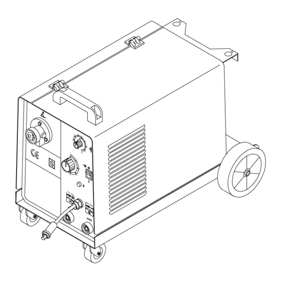
Page 13: Section 3 - Operation
SECTION 3 – OPERATION 3-1. Controls Handle Wire Speed Control 6 Position Voltage Control Power Switch with Pilot Light Thermal Overload Pilot Light Polarity Change Over Cable Negative Power Source Terminal Positive Power Source Connector Work Connection 10 Torch Connector OM-189 107 Page 9... -
Page 14: Section 4 - Maintenance And Troubleshooting
SECTION 4 – MAINTENANCE AND TROUBLESHOOTING 4-1. Routine Maintenance Y Disconnect power before maintaining. 3 Months Repair or replace Replace unreadable labels. cracked weld cable. Clean and tighten weld terminals. 6 Months Blow out or vacuum inside. During heavy service clean monthly. 4-2. -
Page 15: Troubleshooting
4-3. Troubleshooting Trouble Remedy No weld output; wire does not feed. Be sure line disconnect switch is On (see Section 2-7). Replace building line fuse or reset circuit breaker if open (see Section 2-7). Reset circuit breaker CB1. Secure gun trigger connections. Check and replace Power switch if necessary. -
Page 16: Section 5 - Electrical Diagram
SECTION 5 – ELECTRICAL DIAGRAM 5-1. Integra 151S OM-189 107 Page 12... -
Page 17: Section 6 - Parts List
SECTION 6 – PARTS LIST 6-1. Main Assembly Item Ref. Code Qty. Item Ref. Code Qty. 156022018 VP.0.0.24 056076199 MU.0.0.40 1 656002010 MU.0.0.22 1 156006009 VP.0.0.30 FM230V- 057035005 GS.230V 056061037 MQ.0.0.5 50/60Hz 057098002 MU.0.3 057084040 MU.0.1 TP.1 056159006 MU.0.0.10 1 156007028 VP.0.0.25 T1 (230V- 058021053 MU.1 056054053 MU.0.0.1... - Page 18 Notes...
- Page 19 LIMITED WARRANTY – Subject to the terms and conditions APT, ZIPCUT & PLAZCUT Model Plasma Cutting below, Miller Electric Mfg. Co., Appleton, Wisconsin, Torches warrants to its original retail purchaser that new Miller Remote Controls...
- Page 20 Phone: 414-735-4505 USA & Canada FAX: 920-735-4134 International FAX: 920-735-4125 European Headquarters – United Kingdom Phone: 44 (0) 1204-593493 FAX: 44 (0) 1204-598066 Miller Europe Italy Phone: 39 (0) 2982901 PRINTED IN USA 1999 Miller Electric Mfg. Co. 7/99...
Need help?
Do you have a question about the INTEGRA 151S and is the answer not in the manual?
Questions and answers