
Related Manuals for Miller Electric SuitCase X-TREME 12VS


Summary of Contents for Miller Electric SuitCase X-TREME 12VS
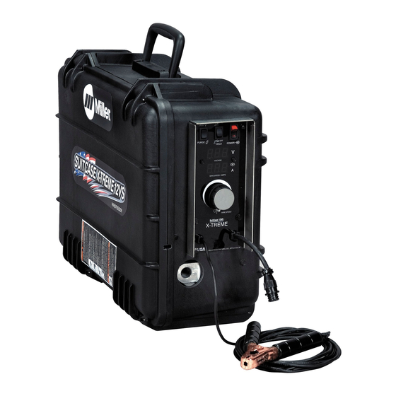
- Page 1 OM-252 203H 2015−09 Processes MIG (GMAW) Welding Flux Cored (FCAW) Welding Description Wire Feeder SuitCase ™ X-TREME 12VS CE And Non-CE Models File: MIG (GMAW) Visit our website at www.MillerWelds.com...
- Page 2 ISO 9001 Quality System Standard. particular model are also provided. Miller Electric manufactures a full line of welders and welding related equipment. For information on other quality Miller products, contact your local Miller distributor to receive the latest full line catalog or individual specification sheets.
-
Page 3: Table Of Contents
TABLE OF CONTENTS SECTION 1 − SAFETY PRECAUTIONS - READ BEFORE USING ....... . . 1-1. -
Page 4: Declaration Of Conformity
DECLARATION OF CONFORMITY for European Community (CE marked) products. MILLER Electric Mfg. Co., 1635 Spencer Street, Appleton, WI 54914 U.S.A. declares that the product(s) identified in this declaration conform to the essential requirements and provisions of the stated Council Directive(s) and Standard(s). -
Page 5: Section 1 − Safety Precautions - Read Before Using
SECTION 1 − SAFETY PRECAUTIONS - READ BEFORE USING som 2013−09 Protect yourself and others from injury — read, follow, and save these important safety precautions and operating instructions. 1-1. Symbol Usage DANGER! − Indicates a hazardous situation which, if Indicates special instructions. - Page 6 D Remove stick electrode from holder or cut off welding wire at FUMES AND GASES can be hazardous. contact tip when not in use. D Wear body protection made from durable, flame−resistant material Welding produces fumes and gases. Breathing (leather, heavy cotton, wool). Body protection includes oil-free these fumes and gases can be hazardous to your clothing such as leather gloves, heavy shirt, cuffless trousers, high health.
-
Page 7: Additional Symbols For Installation, Operation, And Maintenance
1-3. Additional Symbols For Installation, Operation, And Maintenance FIRE OR EXPLOSION hazard. MOVING PARTS can injure. D Do not install or place unit on, over, or near D Keep away from moving parts such as fans. combustible surfaces. D Keep all doors, panels, covers, and guards D Do not install unit near flammables. -
Page 8: California Proposition 65 Warnings
1-4. California Proposition 65 Warnings Welding or cutting equipment produces fumes or gases This product contains chemicals, including lead, known to which contain chemicals known to the State of California to the state of California to cause cancer, birth defects, or other cause birth defects and, in some cases, cancer. -
Page 9: Section 2 − Consignes De Sécurité − Lire Avant Utilisation
SECTION 2 − CONSIGNES DE SÉCURITÉ − LIRE AVANT UTILISATION fre_som_2013−09 Pour écarter les risques de blessure pour vous−même et pour autrui — lire, appliquer et ranger en lieu sûr ces consignes relatives aux précautions de sécurité et au mode opératoire. 2-1. - Page 10 D Ne pas raccorder plus d’une électrode ou plus d’un câble de D Avoir recours à des écrans protecteurs ou à des rideaux pour masse à une même borne de sortie de soudage. Débrancher le protéger les autres contre les rayonnements les éblouissements câble pour le procédé...
-
Page 11: Dangers Supplémentaires En Relation Avec L'installation, Le Fonctionnement Et La Maintenance
DES PIECES DE METAL ou DES LES BOUTEILLES peuvent exploser si elles sont endommagées. SALETES peuvent provoquer des blessures dans les yeux. Les bouteilles de gaz comprimé contiennent du gaz sous haute pression. Si une bouteille est D Le soudage, l’écaillement, le passage de la endommagée, elle peut exploser. - Page 12 LES CHARGES ÉLECTROSTATI- RAYONNEMENT HAUTE QUES peuvent endommager les cir- FRÉQUENCE (H.F.) risque cuits imprimés. provoquer des interférences. D Établir la connexion avec la barrette de terre D Le rayonnement haute fréquence (H.F.) peut avant de manipuler des cartes ou des pièces. provoquer des interférences avec les équi- D Utiliser des pochettes et des boîtes antista- pements de radio−navigation et de com-...
-
Page 13: Proposition Californienne 65 Avertissements
2-4. Proposition californienne 65 Avertissements Les équipements de soudage et de coupage produisent des Ce produit contient des produits chimiques, notamment du fumées et des gaz qui contiennent des produits chimiques plomb, dont l’État de Californie reconnaît qu’ils provoquent dont l’État de Californie reconnaît qu’ils provoquent des mal- des cancers, des malformations congénitales ou d’autres formations congénitales et, dans certains cas, des cancers. - Page 14 OM-252 203 Page 10...
-
Page 15: Section 3 − Definitions
SECTION 3 − DEFINITIONS 3-1. Additional Safety Symbols And Definitions Some symbols are found only on CE products. Warning! Watch Out! There are possible hazards as shown by the symbols. Safe1 2012−05 Do not discard product (where applicable) with general waste. Reuse or recycle Waste Electrical and Electronic Equipment (WEEE) by disposing at a designated collection facility. -
Page 16: Miscellaneous Symbols And Definitions
Do not weld on drums or any closed containers. Safe64 2012−06 Do not remove or paint over (cover) the label. Safe20 2012−05 Drive rolls can injure fingers. Safe32 2012−05 Welding wire and drive parts are at welding voltage during operation − keep hands and metal objects away. Safe33 2012−05 Wear hat and safety glasses. -
Page 17: Section 4 − Specifications
SECTION 4 − SPECIFICATIONS 4-1. Serial Number And Rating Label Location The serial number and rating information for this product is located inside the door. Use rating label to determine input power requirements and/or rated output. For future reference, write serial number in space provided on back cover of this manual. 4-2. -
Page 18: Section 5 − Installation
B. Information On Electromagnetic Fields (EMF) This equipment shall not be used by the general public as the EMF limits for the general public might be exceeded during welding. This equipment is built in accordance with EN 60974−1 and is intended to be used only in an occupational environment (where the general public access is prohibited or regulated in such a way as to be similar to occupational use) by an expert or an instructed person. -
Page 19: Installing Drive Rolls
5-2. Installing Drive Rolls Installing Drive Rolls: Drive Roll Securing Nut Drive Roll Carrier Turn nut one click until lobes of nut Installing Drive Rolls line up with lobes of drive roll carrier. Drive Roll Slide drive roll onto drive roll carrier. Turn nut one click. -
Page 20: Connecting Welding Gun And Voltage Sensing Clamp
5-3. Connecting Welding Gun And Voltage Sensing Clamp Turn Off wire feeder and welding power source. Stop engine on welding generator. Weld voltage is present at voltage sensing clamp when wire feeder and welding power source are on. This condition exists even if wire feeder lights and meters are off. -
Page 21: Connecting Shielding Gas
5-4. Connecting Shielding Gas NOTICE − This feeder has a shield- ing gas filter that requires special attention when cleaning. See Sec- tion 7-3 for proper cleaning instruc- tions. Gas Hose With 5/8-18 Right-hand Thread Fittings Rear View (User−Supplied) Tighten gas hose fitting to a maximum of 100 in. -
Page 22: Selecting Cable Sizes
5-6. Selecting Cable Sizes* Turn off power before connecting to weld output terminals. Do not use worn, damaged, undersized, or repaired cables. NOTICE − The Total Cable Length in Weld Circuit (see table below) is the combined length of both weld cables. For example, if the power source is 100 ft (30 m) from the workpiece, the total cable length in the weld circuit is 200 ft (2 cables x 100 ft). -
Page 23: Installing And Threading Welding Wire
5-7. Installing And Threading Welding Wire Installing Wire And Adjusting Hub Tension: Retaining Nut Hub Tension Adjustment Knob Remove retaining nut, and install spool so hub pin fits spool hole. Reinstall re- Hold wire tightly to keep it taining nut. from unraveling. -
Page 24: Meter Board (Pc20) Dip Switch Settings
5-9. Meter Board (PC20) DIP Switch Settings Display Hold On Displays will hold their last value for five seconds 1 2 3 4 5 after the trigger is released. After the hold times out, the Voltmeter will show open circuit voltage or weld voltage polarity. -
Page 25: Section 6 − Operation
SECTION 6 − OPERATION 6-1. Controls With Meters Power Control Switch Trigger Hold Switch Trigger hold allows operator to weld without hold- ing gun trigger. To use trigger hold function, place trigger hold switch in the ON position. The operator must hold the trigger for a minimum of 2 seconds, but no longer than 6 seconds be- fore releasing it. -
Page 26: Controls Without Meters
6-2. Controls Without Meters Power Control Switch Trigger Hold Switch Trigger hold allows operator to weld without holding gun trigger. To use trigger hold function, place trigger hold switch in the ON position. The operator must hold the trigger for a mini- mum of 2 seconds, but no longer than 6 sec- onds before releasing it. -
Page 27: Wire Speed Dual Schedule
6-3. Wire Speed Dual Schedule Wire Speed Dual Schedule allows the oper- ator to switch between standard wire speed and a reduced wire speed. When activated, the reduced wire speed will be 87.5% of the standard wire speed. Wire Speed Dual Schedule may be activated any time before or during the weld by using a gun with an in- Weld Gun With Internal Mounted... -
Page 28: Wire Speed Control Settings
6-4. Wire Speed Control Settings Ref. 257 488-A Notes OM-252 203 Page 24... -
Page 29: Section 7 − Maintenance & Troubleshooting
SECTION 7 − MAINTENANCE & TROUBLESHOOTING 7-1. Routine Maintenance Disconnect power Maintain more often during before maintaining. severe conditions. n = Check Z = Change ~ = Clean l = Replace Every Replace Replace Damaged Months Damaged Gas Hose Unreadable n Z l Labels Repair Or Replace... -
Page 30: Cleaning Debris From Shielding Gas Filter Fitting
7-3. Cleaning Debris From Shielding Gas Filter Fitting Disconnect power before maintaining. Shielding Gas Filter Fitting Remove fitting from gas valve on back panel of feeder. Blow compressed air through the threaded male end of fitting to dis- lodge debris from internal mesh screen. -
Page 31: Troubleshooting
7-4. Troubleshooting Trouble Remedy Wire does not feed; open-circuit voltage Check power switch S1 and connections, and replace if necessary. available. Check supplementary protector CB1. Reset CB1. Unit overheated. Allow unit to cool. Check sensing lead connection. Check gun trigger plug connection. Check gun trigger. -
Page 32: Diagnostics
Trouble Remedy Gun trigger is pressed, gas does not If a welding arc is not established in 3 seconds, after the gun trigger is activated, the unit will feed wire flow, wire is not energized, wire feeds. without energizing the contactor or gas valve. The unit will feed approximately 35 feet (10.7 meters) of wire, then stop feeding. -
Page 33: Section 8 − Electrical Diagram
SECTION 8 − ELECTRICAL DIAGRAM 252 200-D Figure 8-1. Circuit Diagram For Wire Feeder OM-252 203 Page 29... -
Page 34: Section 9 − Parts List
SECTION 9 − PARTS LIST 39,40 256 891-C Figure 9-1. Complete Assembly Item Diagram Part marking Description Quantity Figure 9-1. Complete Assembly ....Fig 9-2 Panel Assembly Front (Without Meters) . - Page 35 Item Dia. Part Description Mkgs Quantity Figure 9-1. Complete Assembly (Continued) ....Fig 9-4 Drive Assembly, Wire ..........
- Page 36 Hardware is common and not available unless listed. 257 057-B Figure 9-2. Front Panel Assembly without Meters Item Dia. Part Description Mkgs Quantity Figure 9-2. Front Panel Assembly without Meters (Figure 9-1 Item 1) ......Nameplate, Without Meters (Order By Model And Serial Number) .
- Page 37 Hardware is common and not available unless listed. 257 055-A Figure 9-3. Front Panel Assembly with Meters Item Dia. Part Description Mkgs Quantity Figure 9-3. Front Panel Assembly with Meters (Figure 9-1 Item 2) ......Nameplate, With Meters (Order By Model And Serial Number) .
- Page 38 Hardware is common and not available unless listed. 257 016-B Figure 9-4. Drive Assembly, Wire OM-252 203 Page 34...
- Page 39 Item Dia. Part Description Mkgs Quantity Figure 9-4. Drive Assembly, Wire (Figure 9-1 Item 3) ... . . 252214 Motor, Right Angle 24VDC .........
- Page 40 Table 9-1. Drive Roll Guide Base Selection Of Drive Rolls Upon The Following Recommended Usages: 1. V-Grooved Rolls For Hard Wire. 2. U-Grooved Rolls For Soft And Soft Shelled Cored Wires. 3. U-Cogged Rolls For Extremely Soft Shelled Wires (Usually Hard Surfacing Types). 4.
- Page 41 Notes Start Your Professional Over 80,000 trained 400 Trade Square East, Troy, Ohio 45373 Welding Career Now! since 1930! 1-800-332-9448 www.welding.org...
- Page 42 Notes...
- Page 43 LIMITED WARRANTY − Subject to the terms and conditions below, 6 Months — Parts Call Miller Electric Mfg. Co., Appleton, Wisconsin, warrants to its original Batteries retail purchaser that new Miller equipment sold after the effective Bernard Guns (No Labor)
- Page 44 Contact the Delivering Carrier to: File a claim for loss or damage during shipment. For assistance in filing or settling claims, contact your distributor and/or equipment manufacturer’s Transportation Department. © ORIGINAL INSTRUCTIONS − PRINTED IN USA 2015 Miller Electric Mfg. Co. 2015−01...
Need help?
Do you have a question about the SuitCase X-TREME 12VS and is the answer not in the manual?
Questions and answers