Table of Contents
Advertisement
Quick Links
Advertisement
Table of Contents

Subscribe to Our Youtube Channel
Related Manuals for Diamond SDGT/10-CL


Summary of Contents for Diamond SDGT/10-CL
- Page 1 09/2016 Mod: SDGT/10-CL Production code: 646572...
- Page 2 CONVECTION - GAS CONVECTION OVENS INSTALLATION, OPERATION AND MAINTENANCE Page (*) Lingua originale / Original language / Originalsprache / Oorspronkelijke taal / Originalspråk / Original- sprog / Alkuperäinen kieli / Originalspråk / Langue originale / Idioma original / Idioma original / Αρχική γλώσσα...
- Page 3 6-10 GN1/1 GN2/1 90°...
- Page 4 安装图 SCHEMA DI INSTALLAZIONE INSTALLATIONSRITNING 取付図 INSTALLATION DIAGRAM INSTALLATIONSDIAGRAM INSTALLATIONSPLAN 설치 도면 ESQUEMAS DE INSTALAÇAO SCHEMA D'INSTALLATION Ó×ÅÄÉÁÃÑÁÌÌÁÔÁ ÅÃÊÁÔÁÓÔÁÓÇÓ ESQUEMA PARA LA INSTALACIÓN ASENNUSKAAVIOT INSTALLASJONSSKJEMAER INSTALLATIESCHEMA 6 GN 1/1 Mod. 描述 ....页码 Descrizione....Pagina 商品概要 ..ページ Description ....Page 설명 ..... 페이지 Deschreibung ..Seite Description ....Page Descripción .....Pág.
- Page 5 安装图 INSTALLATIONSRITNING SCHEMA DI INSTALLAZIONE 取付図 INSTALLATIONSDIAGRAM INSTALLATION DIAGRAM 설치 도면 INSTALLATIONSPLAN ESQUEMAS DE INSTALAÇAO Ó×ÅÄÉÁÃÑÁÌÌÁÔÁ ÅÃÊÁÔÁÓÔÁÓÇÓ SCHEMA D'INSTALLATION ESQUEMA PARA LA INSTALACIÓN ASENNUSKAAVIOT INSTALLASJONSSKJEMAER INSTALLATIESCHEMA 10 GN 1/1 Mod. 描述 ....页码 Descrizione....Pagina Description ....Page 商品概要 ..ページ Deschreibung ..Seite 설명 ..... 페이지 Description ....Page Descripción .....Pág.
- Page 6 INSTALLATIONSRITNING 安装图 SCHEMA DI INSTALLAZIONE INSTALLATIONSDIAGRAM 取付図 INSTALLATION DIAGRAM ESQUEMAS DE INSTALAÇAO INSTALLATIONSPLAN 설치 도면 Ó×ÅÄÉÁÃÑÁÌÌÁÔÁ ÅÃÊÁÔÁÓÔÁÓÇÓ SCHEMA D'INSTALLATION ASENNUSKAAVIOT ESQUEMA PARA LA INSTALACIÓN INSTALLASJONSSKJEMAER INSTALLATIESCHEMA 10 GN 2/1 Mod. 描述 ....页码 Descrizione....Pagina Description ....Page 商品概要 ..ページ Deschreibung ..Seite 설명 ..... 페이지 Description ....Page Descripción .....Pág.
- Page 7 安装图 INSTALLATIONSRITNING SCHEMA DI INSTALLAZIONE 取付図 INSTALLATIONSDIAGRAM INSTALLATION DIAGRAM 설치 도면 INSTALLATIONSPLAN ESQUEMAS DE INSTALAÇAO Ó×ÅÄÉÁÃÑÁÌÌÁÔÁ ÅÃÊÁÔÁÓÔÁÓÇÓ SCHEMA D'INSTALLATION ASENNUSKAAVIOT ESQUEMA PARA LA INSTALACIÓN INSTALLASJONSSKJEMAER INSTALLATIESCHEMA 20 GN 1/1 Mod. 描述 ....页码 Descrizione....Pagina 商品概要 ..ページ Description ....Page Deschreibung ..Seite 설명 ..... 페이지 Description ....Page Descripción .....Pág.
- Page 8 安装图 INSTALLATIONSRITNING SCHEMA DI INSTALLAZIONE 取付図 INSTALLATIONSDIAGRAM INSTALLATION DIAGRAM ESQUEMAS DE INSTALAÇAO INSTALLATIONSPLAN 설치 도면 Ó×ÅÄÉÁÃÑÁÌÌÁÔÁ ÅÃÊÁÔÁÓÔÁÓÇÓ SCHEMA D'INSTALLATION ASENNUSKAAVIOT ESQUEMA PARA LA INSTALACIÓN INSTALLASJONSSKJEMAER INSTALLATIESCHEMA 20 GN 2/1 Mod. Descrizione....Pagina 描述 ....页码 Description ....Page 商品概要 ..ページ Deschreibung ..Seite 설명 ..... 페이지 Description ....Page Descripción .....Pág.
-
Page 9: Table Of Contents
CONVECTION GAS OVENS INSTALLATION AND OPERATING INSTRUCTIONS (for the United Kingdom) Summary Page - Installation diagrams............4 7.3 REPLACING THE GAS VALVE ........ 45 APPLIANCE IDENTIFICATION.......... 37 7.4 GAS VALVE ADJUSTMENT ........45 7.5 TABLE 2: NOZZLES AND ADJUSTMENTS / GAS I. -
Page 10: General Characteristics
I. GENERAL CHARACTERISTICS 1. TABLE 1: TECHNICAL DATA 6GN2/1 10 GN 1/1 10 GN 2/1 20 GN 1/1 20 GN 2/1 6 GN 1/1 (AOS061E) 253,3 344,25 ° ° ° ° ° 50 / 60 50 / 60 50 / 60 50 / 60 50 / 60 0,25... -
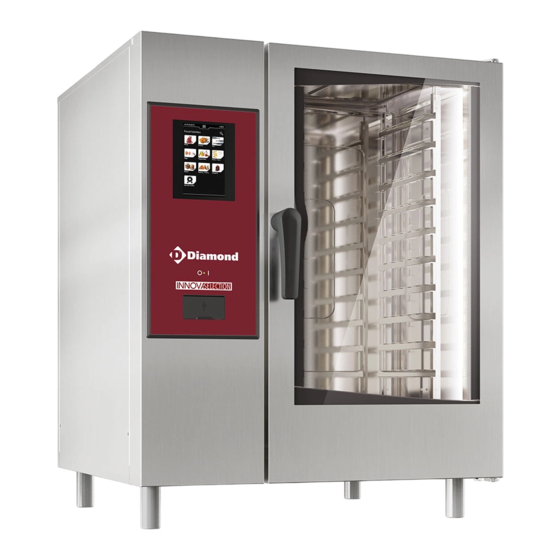
Page 11: Appliance Description
Information on sound emissions: The functional components of the appliances in question have a noise level not exceeding 70 dB (A). • Before installing and using the ap- pliance, carefully read this handbook as The oven model is specifi ed at the PNC fi eld on the "Technical it provides important information and Data"... -
Page 12: Residual Risks
Failure to use the personal protection equipment by operators, Hz ......power supply frequency specialised technicians or users can involve exposure to chemical kW ......max. power input risk and possible damage to health. A ......current absorption EL: ......[H] electrical prearrangement Cat ...... -
Page 13: Installation Instructions
II. INSTALLATION INSTRUCTIONS right side and back must remain 10 cm from any surface. Attention: The external panels of the oven must be • Position the appliance on a fl at surface and, if necessary, adjust removed for the operations described in this section. the height of the worktop by means of the adjustable feet. -
Page 14: Instructions Regarding The Exhaust System
CONSTRUCTION TYPE KEY: Manifold / draught damper accessory (to be ordered from the manufacturer) Omissis Compartment convector burnt gas outlet Adapter ring for commercial ducts (to be ordered from the manufacturer) Conical sections for single outlet (accessory not mandatory) Tmax=350°C Fixing screws (supplied);... -
Page 15: Power Cable Installation
4.1 POWER CABLE INSTALLATION WATER CHARACTERISTICS INLET "CWI1" To guarantee correct appliance operation, several water To connect the power cable to the appliance, proceed as follows: treatment systems may have to be installed. For that purpose, Model 6 - 10 - 20 GN see the instructions of the following Flow Chart : •... -
Page 16: Water Draining System
6. GAS CONNECTION CHECK SUPPLY PRESSURE INPUT "CWI1" AND "CWI2" The pressure measured upstream of the oven (and downstream of any WATER FILTRATION SYSTEMS installed) must be between 150 and 450 kPa (1.5 - 4.5 bar / 22-65 psi) measured in dynamic 6.1 INSTRUCTIONS conditions, i.e. -
Page 17: Conversion To Another Type Of Gas
7. CONVERSION TO ANOTHER TYPE OF GAS • Loosen the screw "D" relevant to the gas valve pressure point and connect a pressure gauge with minimum resolution of 1 Pa to it; • Remove adjustment screw cap "E1". Attention: The appliance is factory set for a type of •... - Page 18 7.5 TABLE 2: NOZZLES AND ADJUSTMENTS / GAS TYPES FIGURE 2a - 2b n° of GRIDS 6 GN1/1 10 GN1/1 10 GN2/1 20 GN1/1 20 GN2/1 ° ° ° ° ° CONVECTOR ° REFERENCE ø ø ø ø ø Diaphragm 5,25 G31 L.P.G.
-
Page 19: Gas Type Sticker
7.6 GAS TYPE STICKER The burner goes out (the message "burn" appears on the display TM, see "Operating instructions" chap. 5). After the conversion to a different type of gas, apply the sticker for Possible causes: the new gas on the oven in place of the existing one. The sticker - Power supply polarity (Phase/Neutral) inverted. -
Page 20: Operating Instructions
III. OPERATING INSTRUCTIONS Before starting the appliance, carefully read this handbook. The MODELS WITH DOUBLE OPENING SYSTEM (on request) instructions and information given in it are important for correct The oven has a double opening system to prevent being exposed and optimum oven use. -
Page 21: Description Of Control Panel
DESCRIPTION OF CONTROL PANEL ..Hot air cycle with compartment vent closed: for cooking with high humidity. (Default setting) The control panel has the following controls: ON/OFF oven switch. _______________ Digital thermostat for control of compartment temperature. Timer for control of cooking time. - Page 22 MULTIPHASE INFORMATION - NOTES - WARNINGS Cooking with phases in sequence: for setting Information area cooking programs with several phases in automatic Area displaying current sequence (max. 15 phases). Status, Error, Warning and Utility information. Active pause phase Warning light signalling oven door open. Add pause phase: by entering a time value in this mode it is possible to delay the start of cooking pro- grams or include a pause between two cycles (e.g.
- Page 23 Upload data in oven from USB port Download data from oven on USB port Restore oven confi guration to default values (Reset) Identity Card: Oven identifi cation giving rating data and software version. This item is located in the Set- tings drawer.
-
Page 24: Oven Use
OVEN USE 4. CONTROL PANEL USE 4.2 SWITCHING THE OVEN OFF To switch the oven off, press the button O (O - I) of the following Foreword: switch: When selecting certain functions, the initial status is restored if no button is pressed within 15 seconds (approx.). O °... -
Page 25: Manual
In this way a cooking cycle has been set; now, just close the door 4.4 MANUAL and touch START to start the Cycle. The PREHEATING stage starts, after which the message "LOAD" appears, indicating to place food in the oven; close the door to start cooking. - Page 26 The functions in MANUAL Cooking mode are as follows: cycle HOT AIR HUMIDIFICATION TEMPERATURE TIME CORE PROBE adjustable x (max. 8 hours) x (from 10° to 99°) ---- > compartment vent open ---- > compartment vent closed x ---- > Eco Delta * x (from 1°...
- Page 27 phase number UTILITIES (see page 48) Hot Air cycle cycle HOT AIR humidifi cation 160° temperature (C°) Fan speed * 0:30 cooking phase time (0 hours : 30 minutes) Injection of water in compartment x (from 10sec. to 120sec.) Also, one or more phases can be skipped during cooking; press Programmed Start the symbol next to phase 3 (ex.
- Page 28 4.4.4 ECODELTA 4.4.3 ADVANCED MULTITIMER The Advanced MultiTimer function is the same as the MultiTimer The ECO DELTA function enables cooking without har- with the addition of the following functions: ming the food with high temperatures; this ensures more gentle and more even cooking, with less weight loss.
- Page 29 4.4.6 CORE PROBE USE 4.4.7 END OF COOKING (PRODUCT CORE TEMPERATURE CONTROL) At the end of the set time, the cooking cycle automatically stops The core probe allows accurate control of the core temperature and the oven buzzer sounds continuously. of the product being cooked.
-
Page 30: Programs
4.5 PROGRAMS 4.5.2 START PROGRAM Press the button of the Program Name on the Program List to access the Start screen and set the cooking parameters or start the program. The PROGRAMS control mode is used for already carrying out stored programs (or recipes), storing new ones and managing them inside a list. -
Page 31: Mt Programs
ATTENTION: This screen will show checkmarks on the categories to which the program is already linked. MANAGE PROGRAMS If the checkmarks are removed from these categories the program This function allows the programs to be managed using the fol- will be unlinked. lowing buttons: 5) Press “Save”... -
Page 32: Cleaning
MANAGE PRESET PROGRAMS DRAWER This function is used to manage presets with the following buttons: The Programs drawer contains functions for the Programs and - Select All = to select all the Presets of all Programs. Presets. - Show Selected = to select only the relevant Presets. - Show Program = to select the Presets inside the various programs. -
Page 33: Settings
Warning: 4.8 SETTINGS In case of complete emptying of the detergent and/or rinse aid containers or emptying of their supply tubes, the CLEANING SYSTEM cycle must be started after fi rstly doing the CLEAN 1 Select one of the following items: cycle, then the same or other cycles. - Page 34 Timer/Temperature dialogs DATE TIME Short cooking Enter the date and time with the +/- sign (or with the keypad). MultiTimer cooking Eco-delta cooking Settings Settings Show core probe with timed cooking Hold Date Time Default convection temp.
-
Page 35: Switching Off In Case Of A Fault
6. CLEANING AND MAINTENANCE 4.8.1 MAINTENANCE TECHNICAL ASSISTANCE • Have the appliance fully checked periodically (at least once a year). For that purpose, it is advisable to stipulate a maintenance Technical assistance contract. By pressing this button a password is requested for for AUSTRALIA accessing the area reserved for authorised technical For service and spare parts, please contact:... -
Page 36: Replacing Consumable Components
ATTENTION: • Do not clean the stainless steel with steel wool, brushes or The warranty does not cover damage caused by the use of deter- scrapers in common steel, as they could deposit ferrous particles gents and rinse aids not complying with the above characteristics. which oxidise, causing rust spots. -
Page 37: Particular Cleaning
6.2 PARTICULAR CLEANING Discharge system cleaning and effi ciency check Periodically clean the drain pipe, checking for any obstructions involving the draining of water. Cleaning the door internal glass (Fig. 5) These operations must be donet with the door glass cold, without using abrasive detergents or rags.
Need help?
Do you have a question about the SDGT/10-CL and is the answer not in the manual?
Questions and answers