
Subscribe to Our Youtube Channel
Related Manuals for Kampmann Ultra Allround


Summary of Contents for Kampmann Ultra Allround
- Page 1 Ultra Allround ► Assembly, installation and operating instructions Keep these instructions in a safe place for future use! Issue06/23EN SAP No.1816834...
-
Page 3: Table Of Contents
6.2 Installation height and throws ....................... 15 6.3 Minimum clearances..........................15 6.4 Installation............................. 16 6.4.1 Ultra suspension points ..........................16 6.4.2 Installation of the Ultra Allround ....................... 18 6.5 Installation............................. 20 6.5.1 Connection to the pipe network ........................ 21 6.6 Condensation connection ........................22 6.6.1 Condensate drainage using a condensate pump .................. - Page 4 7.2.1 Connection (*00)............................23 7.3 KaControl (*C1) ............................. 33 7.3.1 KaController installation..........................33 7.3.2 Connection (*C1)............................34 8 Pre-commissioning checks....................42 9 Operation..........................43 9.1 Operation of electromechanical control ....................43 9.2 Operation of the KaController........................ 46 9.2.1 Function keys, display elements ........................ 47 10 Maintenance .........................
-
Page 5: General
Ultra Allround Assembly, installation and operating instructions General About these instructions These instructions ensure the safe and efficient handling of this equipment. These instructions form an integral part of the equipment and have to be kept in the direct vicinity of the equipment and available to personnel at all times. -
Page 6: Safety
Ultra Allround Assembly, installation and operating instructions Safety This section provides an overview of all important safety aspects to ensure optimum protection of personnel as well as safe and trouble-free operation. In addition to the safety instructions in these operating instructions, the valid safety, accident pre- vention and environmental protection regulations must be observed for the area of use of the unit. - Page 7 Ultra Allround Assembly, installation and operating instructions Water quality pH value (at 20 °C) Conductivity (at 20 °C) μS/cm < 700 Oxygen content (O mg/l < 0.1 Hardness °dH 4-8.5 Sulphur ions not measurable Sodium ions (Na mg/l < 100...
-
Page 8: Risk From Electrocution
Ultra Allround Assembly, installation and operating instructions IMPORTANT NOTE! Danger of frost in cooling mode! There is a risk of the heat exchanger freezing when used in unheated rooms. Make sure that the unit is equipped with a frost protection sensor and/or thermostat in this case. -
Page 9: Personnel Requirements - Qualifications
Ultra Allround Assembly, installation and operating instructions Personnel requirements - Qualifications Expertise The installation of this product requires specialist knowledge of heating, cooling, ventilation, installation and electrical engin- eering. This knowledge, generally learned in professional training in one of the fields mentioned above, is not described sep- arately. -
Page 10: Transport, Storage And Packaging
IMPORTANT NOTE! Warranty claims can only be made within the applicable period for complaints. (More information is avail- able in the T&Cs on the Kampmann website) IMPORTANT NOTE! 2 people are needed to transport the unit. Wear personal protective clothing when transporting the unit. -
Page 11: Storage
The packaging serves as a transport aid as well as dust and assembly protection. Only remove the packaging properly shortly before commissioning. If the Ultra Allround is carried/mounted without the outer packaging, lift the device only by the underside! -
Page 12: Technical Data
Ultra Allround Assembly, installation and operating instructions Technical data Size Water capacity [l] Weight [kg] Sound power level [db(A)] <70 <73 Diameter [mm] 1300 1300 Height [mm] Tab. 4: Technical specifications Ultra Allround... -
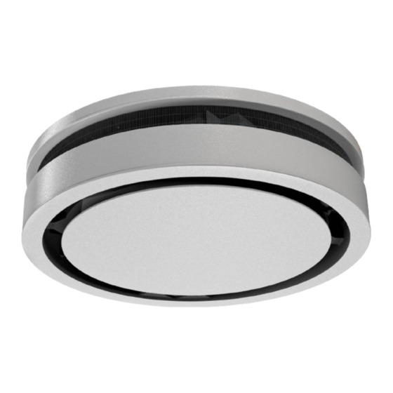
Page 13: Construction And Function
Brief description Ultra Allround ceiling-mounted unit heaters, heating and/or cooling models, are used for the decentralised heating and vent- ilation of halls, exhibition halls and sales rooms. Air is drawn in through the radial fan and is blown through the circular heat exchanger into the room. -
Page 14: Wear Parts List
Ultra Allround Assembly, installation and operating instructions Wear parts list Figure Article Properties For use with Art. no. Size 1 For direct mounting on the Recirculating air filter ele- unit intake area with recir- ment culating air units, coarse Size 2... -
Page 15: Installation And Wiring
Ultra Allround Assembly, installation and operating instructions Installation and wiring Requirements governing the installation site Only install and assemble the unit if the following conditions are met: Make sure that the unit is securely suspended/standing. Ensure that the airflow can circulate freely. -
Page 16: Minimum Clearances
When using accessories or for maintenance purposes, it is essential to observe the minimum distances! Fig. 3: Minimum distances Ultra Allround Installation Appropriate technical lifting equipment or 4 people are required for installation. -
Page 17: Ultra Suspension Points
Ultra Allround Assembly, installation and operating instructions 6.4.1 Ultra suspension points Fig. 4: Ultra Allround suspension points Size 1 Size 2 A [mm] B [mm] C [mm]... -
Page 18: Installation Of The Ultra Allround
6.4.2 Installation of the Ultra Allround The packaging serves as a transport aid as well as dust and assembly protection. Only remove the packaging properly shortly before commissioning. If the Ultra Allround is carried/mounted without the outer packaging, lift the device only by the underside! - Page 19 Ultra Allround Assembly, installation and operating instructions Fig. 5: Diagram: Suspension of the Ultra Allround Use threaded rods (by others) to suspend the unit by the 4 mounting brackets. Lock the threaded rods in place with nuts and washers.
-
Page 20: Installation
Ultra Allround Assembly, installation and operating instructions Installation Hydraulic connection Note the following points when connecting the hydraulic side: Install and test safety components (expansion vessels, pressure relief valves and overflow valves). Route condensation lines with a sufficient cross-section without bends and narrow sections with a gradient to the in situ waste water pipe. -
Page 21: Connection To The Pipe Network
(for example when disassembling the fan). With certain unit designs, the fans can only be replaced once the unit has been completely disassembled. Fig. 6: Connection dimensions Ultra Allround Size 1... -
Page 22: Condensation Connection
Ultra Allround Assembly, installation and operating instructions Condensation connection 6.6.1 Condensate drainage using a condensate pump The water is drawn off by the condensate pump and discharged along a hose connected on the pressure side. Depending on conditions on site, the water can be discharged into drainage lines, possibly with a trap connection. The hose length from the unit is 700 mm, with a diameter of 6 mm (1/4”). -
Page 23: Electrical Connection
Ultra Allround Assembly, installation and operating instructions Electrical connection Maximum electrical rating values Electromechanical version Item no. Rated Power fre- Active Rated cur- Leakage cur- Maximum IP protec- Protection voltage [V] quency [Hz] power [kW] rent [A] rent [mA] backup fuse... - Page 24 Ultra Allround Assembly, installation and operating instructions Fig. 9: Control board 230 V voltage Optional: condensate pump power supply Valve actuator, optional damper actuator and optional condens- Heating / cooling switch-over ate alarm 0 - 10 V control and potential-free fault alarms (motor and con- densate) Description of the control board Rev.
- Page 25 Ultra Allround Assembly, installation and operating instructions Section of the printed circuit board Description Terminal block X2 (control voltage / fault alarm): UC/GND 0-10 V DC signal for EC fan speed continuously variable A+/B- External modbus connection for EC fan f.e1/f.e2 potential-free motor alarm contact 30 V DC / 2 A...
- Page 26 Ultra Allround Assembly, installation and operating instructions Section of the printed circuit board Description Terminal block X7 (fan / condensate pump power supply connection): 230 V AC / 50 Hz Fan and condensate pump Terminal block X10 (output voltage): Output voltage 230 V AC / 50 Hz...
- Page 27 Ultra Allround Assembly, installation and operating instructions...
- Page 28 Ultra Allround Assembly, installation and operating instructions...
- Page 29 Ultra Allround Assembly, installation and operating instructions...
- Page 30 Ultra Allround Assembly, installation and operating instructions...
- Page 31 Ultra Allround Assembly, installation and operating instructions...
- Page 32 Ultra Allround Assembly, installation and operating instructions...
-
Page 33: Kacontrol (*C1)
Ultra Allround Assembly, installation and operating instructions KaControl (*C1) 7.3.1 KaController installation Fig. 10: Installation of flush-mounted back box Electrical connection Connect the KaController to the nearest KaControl unit in line with the wiring diagram. The maximum bus length between the KaController and the KaControl master unit is 30 m. -
Page 34: Connection (*C1)
Ultra Allround Assembly, installation and operating instructions 7.3.2 Connection (*C1) General information Route all low voltage cables along the shortest route. Ensure that low-voltage and power cables are separated, using metal partitions on cable harnesses. Wrong! Use only shielded cables as low-voltage and bus cables. - Page 35 Ultra Allround Assembly, installation and operating instructions Circuit description All units need a 230 V AC power supply. A lockable repair switch is always fitted and connected to the electrical housing. Factory-fitted actuators are wired to the terminals. The appropriate terminals are available for valve actuators.
- Page 36 Ultra Allround Assembly, installation and operating instructions Description of the control board Rev. 1.06 (*C1) Section of the printed circuit board Description Terminal block X8 (230 V AC feed) 230 V AC / 50 Hz feed PE, N, L Terminal block X2 (control voltage / fault alarm): f.e1/f.e2 potential-free motor alarm contact 30 V DC / 2 A...
- Page 37 Ultra Allround Assembly, installation and operating instructions Section of the printed circuit board Description Terminal block X10 (output voltage): Output voltage 230 V AC / 50 Hz Possible indication: – Repair switch activated – Fuse or electrical unit failure Visual display:...
- Page 38 Ultra Allround Assembly, installation and operating instructions...
- Page 39 Ultra Allround Assembly, installation and operating instructions...
- Page 40 Ultra Allround Assembly, installation and operating instructions...
- Page 41 Ultra Allround Assembly, installation and operating instructions...
-
Page 42: Pre-Commissioning Checks
Ultra Allround Assembly, installation and operating instructions Pre-commissioning checks When commissioning the device for the first time, ensure that all the necessary requirements are met so that the device can function safely and in accordance with its intended use. Structural tests Check that the unit is securely standing and fixed. -
Page 43: Operation
Ultra Allround Assembly, installation and operating instructions Operation Operation of electromechanical control Speed controller, type 30510 The speed controller is used to activate the fan and pre-set the fan speed. Actu- ation of a thermoelectric shut-off valve is not possible. - Page 44 Ultra Allround Assembly, installation and operating instructions Clock thermostat 230 V, type 30256 Electronic clock thermostat for 2- and 4-pipe applications, surface-mounted wall installation on a flush-mounted box in visually unobtrusive design Operation using 4 sensor keys Timer with automatic summer/winter changeover...
- Page 45 Ultra Allround Assembly, installation and operating instructions Climate controller, black, type 196000148942 for 2- and 4-pipe applications, surface-mounted wall installation on a flush- mounted box with a visually unobtrusive design with 2.5” LCD display and high-quality glass finish with capacitive keys...
- Page 46 Ultra Allround Assembly, installation and operating instructions Climate controller, black, type 196000148944 with Modbus interface for 2- and 4-pipe applications, surface-mounted wall installation on a flush- mounted box with a visually unobtrusive design with 2.5” LCD display and high-quality glass finish with capacitive keys...
-
Page 47: Operation Of The Kacontroller
Ultra Allround Assembly, installation and operating instructions Operation of the KaController The following information is limited to the key content on the operation of the KaController and KaControl system. More in- formation is included separately in the KaControl SmartBoard user manual. - Page 48 Ultra Allround Assembly, installation and operating instructions KaController without operating keys (one-button operation) type 3210001 1. Display with LED background lighting 2. Navigator dial Change settings Call up menus Fig. 24: KaController type 3210001 KaController, black without function keys (one-button opera- tion) type 3210006 1.
-
Page 49: Maintenance
Ultra Allround Assembly, installation and operating instructions Maintenance 10.1 Securing against reconnection DANGER! Risk of death by unauthorised or uncontrolled restart! Unauthorised or uncontrolled restarting of the equipment can result in serious injury or death. Before restarting, ensure that all safety devices are fitted and working properly and that there is no haz- ard to humans. -
Page 50: Visual Checks
Ultra Allround Assembly, installation and operating instructions 10.3 Maintenance work 10.3.1 Visual checks Clean the heat exchanger. Check the heat exchanger for soiling and carefully vacuum if necessary. Avoid damage to the pipework and fins. 10.3.2 Clean the inside of the unit Check all elements that come into contact with air (internal surfaces of the unit, outlet elements etc.) for dirt or deposits dur-... -
Page 51: Dismantling The Housing Cover
Ultra Allround Assembly, installation and operating instructions 10.3.3 Dismantling the housing cover Turn the housing cover anti-clockwise and remove. Fig. 27: Removing the housing cover Remove the safety cables from the base plate. Put the cover aside and refit once revision work has been completed. -
Page 52: Cleaning The Condensate Pump
Ultra Allround Assembly, installation and operating instructions 10.3.5 Cleaning the condensate pump Remove the inspection opening cover to access the condensate pump. Fig. 31: Inspection opening cover Loosen the cable connections to the condensate pump. Remove and clean the condensate pump. -
Page 53: Replacing The Filter
Ultra Allround Assembly, installation and operating instructions 10.3.6 Replacing the filter. CAUTION! Risk of injury from sharp metal housing! The inner metal of the casing can have sharp edges. Wear suitable protective gloves. -
Page 54: Faults
Ultra Allround Assembly, installation and operating instructions Faults The following chapter describes possible causes of faults and the work needed to rectify them. Should faults occur frequently, shorten the maintenance intervals in line with the actual loading on the unit. -
Page 55: Kacontrol Faults
Ultra Allround Assembly, installation and operating instructions 11.2 KaControl faults Code Alarms Priority Faulty control sensor. Motor fault. Room frost protection. Condensation alarm. General alarm. Sensor AI1, AI2 or AI3 faulty. Unit frost protection. EEPROM error. Offline slave in the CAN bus network. -
Page 56: List Of Kacontrol Parameters
Ultra Allround Assembly, installation and operating instructions List of KaControl parameters 12.1 KaController parameter list Para- Function Standard Min. Max. Unit Comment meter Address in Mod- t001 Serial address bus network Baud rate 0 = Baud rate 4800 t002 1 = Baud rate 9600... -
Page 57: Certificates
Ultra Allround Assembly, installation and operating instructions Certificates EU-Konformitätserklärung EU Declaration of Conformity Déclaration de Conformité CE Deklaracja zgodności CE EU prohlášení o konformite KAMPMANN Wir (Name des Anbieters, Anschrift): GMBH & Co. KG Friedrich-Ebert-Str. 128-130 We (Supplier’s Name, Address):... - Page 58 Ultra Allround Assembly, installation and operating instructions Gemäß den Bestimmungen der Richtlinien: Following the provisions of Directive: Conformément aux dispositions de Directive: Zgodnie z postanowieniami Dyrektywy: Odpovídající ustanovení směrnic: 2014/30/EU EMV-Richtlinie 2014/35/EU Niederspannungsrichtlinie 2009/125/EG ErP-Richtlinie 2016/2281 EU Durchführungsverordnung für Luftheizungsprodukte, Kühlungsprodukte, Prozesskühler mit hoher Betriebstemperatur und...
- Page 59 Ultra Allround Assembly, installation and operating instructions Table Tab. 1 Limits of operation ..............................6 Tab. 2 Operating voltage ..............................6 Tab. 3 Water quality................................7 Tab. 4 Technical specifications ............................12 Tab. 5 Electrical specifications Ultra..........................23 Tab. 6 Wiring of bus lines ..............................
- Page 60 Land Kontakt Country Contact Kampmann GmbH & Co. KG Kampmann UK Ltd. Friedrich-Ebert-Str. 128 - 130 Dial House, Govett Avenue 49811 Lingen (Ems) Shepperton, Middlesex, TW17 8AG T +49 591/ 7108-660 T +44 1932/ 228592 Germany Great Britain F +49 591/ 7108-173 F +44 1932/ 228949 E export@kampmann.de...
Need help?
Do you have a question about the Ultra Allround and is the answer not in the manual?
Questions and answers