
Related Manuals for Kampmann Venkon XL


Summary of Contents for Kampmann Venkon XL
- Page 1 Venkon XL ► Assembly, installation and operating instructions Keep these instructions in a safe place for future use! Issue07/23EN SAP No.1809237...
-
Page 3: Table Of Contents
Table of contents 1 General ..........................5 1.1 About these instructions ........................1.2 Explanation of Symbols.......................... 2 Safety............................ 6 2.1 Correct use............................. 2.2 Limits of operation and use........................2.3 Risk from electrocution!......................... 2.4 Personnel requirements - Qualifications ....................2.5 Personal Protective Equipment ......................3 Transport, storage and packaging.................. - Page 4 Cabling, Venkon XL (*00), control by Climate Controller 30256, with condensate pump ......43 7.2.6 Cabling, Venkon XL (*00), control by Climate Controller type 148941/148942 ........44 7.2.7 Cabling, Venkon XL (*00), control by Climate Controller type 148941/148942, with condensate pump .. 45 7.3 KaControl (*C1) ............................. 46 7.3.1 KaController installation..........................46 7.3.2...
-
Page 5: General
Venkon XL Assembly, installation and operating instructions General About these instructions These instructions ensure the safe and efficient handling of this equipment. These instructions form an integral part of the equipment and have to be kept in the direct vicinity of the equipment and available to personnel at all times. -
Page 6: Safety
Venkon XL Assembly, installation and operating instructions Safety This section provides an overview of all important safety aspects to ensure optimum protection of personnel as well as safe and trouble-free operation. In addition to the safety instructions in these operating instructions, the valid safety, accident pre- vention and environmental protection regulations must be observed for the area of use of the unit. - Page 7 Venkon XL Assembly, installation and operating instructions Limits of operation and use Operating limits Min./max. water temperature °C/°F 4-90 Min./max. air intake temperature °C/°F 6-40 Min./max. air humidity 20-60 Min. operating pressure bar/kPa Max. operating pressure bar/kPa/psi 10/1000 Min./max. glycol content 0-50 Tab. 1: Operating limits...
-
Page 8: Risk From Electrocution
Venkon XL Assembly, installation and operating instructions IMPORTANT NOTE! Danger of frost in cooling mode! There is a risk of the heat exchanger freezing when used in unheated rooms. Make sure that the unit is equipped with a frost protection sensor and/or thermostat in this case. -
Page 9: Personnel Requirements - Qualifications
Venkon XL Assembly, installation and operating instructions Personnel requirements - Qualifications Expertise The installation of this product requires specialist knowledge of heating, cooling, ventilation, installation and electrical engin- eering. This knowledge, generally learned in professional training in one of the fields mentioned above, is not described sep- arately. -
Page 10: Transport, Storage And Packaging
IMPORTANT NOTE! Warranty claims can only be made within the applicable period for complaints. (More information is avail- able in the T&Cs on the Kampmann website) IMPORTANT NOTE! 2 people are needed to transport the unit. Wear personal protective clothing when transporting the unit. -
Page 11: Storage
Venkon XL Assembly, installation and operating instructions Storage Store packaging under the following conditions: Do not store outdoors. Store in a dry and dust-free place. Store in a frost-free place. Do not expose to aggressive media. Protect from direct sunlight. -
Page 12: Technical Data
[dB(A)] 39 - 65 39 - 64 41 - 67 40 - 65 level Tab. 4: Technical specifications Venkon XL 230 V at LPHW 75 / 65°C, t = 20°C at LPHW 120 / 100°F, t =68°F at CHW 7/12°C, t = 27 °C, 50% relative humidity for car 45/55 °F, t... -
Page 13: Construction And Function
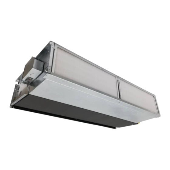
Venkon XL Assembly, installation and operating instructions Construction and function Overview Fig. 1: Venkon XL at a glance (example ceiling version) Float switch Water connection Actuator Valve condensate tray Condensate pump Filter Main condensate drip tray Control (hidden) Heat exchanger... -
Page 14: Brief Description
Brief description Venkon XL are decentralised units for the heating, cooling and filtering of air, for use in hotels, offices and business premises, among others. Secondary air is drawn in filtered by the fan and passed through the copper/aluminium heat exchanger. Here the air is either heated or cooling depending on the temperature of the water in the heat exchanger. -
Page 15: Installation And Wiring
Venkon XL Assembly, installation and operating instructions Installation and wiring Definition of the connection side Example ceiling mounting, left connection left Example ceiling mounting, right connection Fig. 2: Ceiling mounting, left and right connection Example wall mounting, left connection Example wall mounting, right connection... -
Page 16: Requirements Governing The Installation Site
Venkon XL Assembly, installation and operating instructions Requirements governing the installation site Only install and assemble the unit if the following conditions are met: Make sure that the wall/ceiling is sufficiently load-bearing to take the weight of the unit (Technical data [} 12]). -
Page 17: Installation
Consider the occupied zone when installing/suspending the units. Do not expose people to the direct air flow. Position the unit accordingly and adjust the air outlet if required. IMPORTANT NOTE! Sound insulation Provide for sound isolation between the Venkon XL and the adjacent building if required. - Page 18 Once the basic unit has been aligned, prevent the fixing material from coming loose. Venkon XL are fixed per unit at 4 points on the ceiling or on a construction provided by the customer. For this purpose, the devices are suspended from the suspension brackets, e.g. from threaded rods (M8).
-
Page 19: Installation Of Casing
Venkon XL Assembly, installation and operating instructions 6.4.2 Installation of casing Size 1 Size 2 Size 3 Size 4 Fig. 5: Views cladding (simplified representation) The cladding depth X for all sizes is 275 mm / 10.8 inches. By means of the holes in the side panels (see detail X), the cladding can be fixed to the wall for better fixation. - Page 20 Venkon XL Assembly, installation and operating instructions Fit the fixing brackets for the casing. Glue the spacers; maintain a min. distance of 2 cm from above to prevent the edge of the casing from colliding with the spacers. Position the casing on the basic unit.
-
Page 21: Installation Of Sheet Steel Accessories
Venkon XL Assembly, installation and operating instructions 6.4.3 Installation of sheet steel accessories Overview, air side steel sheet accessories Fig. 6: Schematic layout of steel sheet accessories for ceiling mounting Air duct bend 90° Splitter silencer Elastic connecting piece Flex pipe connection unit Ø 198 mm (other diameters available... - Page 22 Venkon XL Assembly, installation and operating instructions Figure Description Dimensions [mm] 1320 1670 Air duct bend 90° 1280 1630 1320 1670 Elastic connecting piece 1280 1630 9 0 0 Inspection hatch with frame / 1 2 9 5 0 / 1 6...
- Page 23 Venkon XL Assembly, installation and operating instructions Frame connection dimensions Size 1 Size 2 Size 3 Size 4 Fig. 7: Frame connection dimensions...
-
Page 24: Installation
When using the units without filters, ensure that the unit is operated at a maximum of 7.3 V, otherwise condensate may drip. This will not happen with Kampmann filters installed. When using filters not approved by the manufacturer, no guarantee regarding the performance specifications can be... -
Page 25: Connection To The Pipe Network
Venkon XL Assembly, installation and operating instructions 6.5.1 Connection to the pipe network The supply and return connections are located on the left or right side of the unit, as seen in the direction of the air flow. The piping must be laid in such a way that no mechanical stresses are transferred to the heat exchanger and the accessibility of the unit during maintenance and repair work is not impaired. - Page 26 Venkon XL Assembly, installation and operating instructions Wall unit Wall unit Ceiling unit, right connection Right connection Left connection in in in in in in in in in in in in Ceiling unit, left connection in in in in A: Venting heating for size 1 - 4...
- Page 27 Venkon XL Assembly, installation and operating instructions Dimensions [mm], left connection side Dimensions [mm], right connection side ø15 ø15 ø15 ø15 Left side view, Left side view, Right side view, Right side view, 2-pipe 4-pipe 4-pipe 2-pipe Dimensions [inch], left connection side Dimensions [inch], right connection side ø0.6...
-
Page 28: Overview Of Valve Kits
Venkon XL Assembly, installation and operating instructions 6.5.2 Overview of valve kits Accessories recirculation basic unit, water side, factory mounted on base unit Mounting water con- 2-pipe version with nection left preset 2-way valve, Item no. Suitable for all sizes... -
Page 29: Connection Of 2-Way Valve Kit
Venkon XL Assembly, installation and operating instructions 6.5.3 Connection of 2-way valve kit 2-way valve kit, wall mounting, 2-pipe, left 2-way valve kit, wall mounting, 4-pipe, left connection connection side side Front view Side view Front view Side view Bottom view... - Page 30 Venkon XL Assembly, installation and operating instructions 2-way valve kit, ceiling mounting, 2-pipe, left 2-way valve kit, ceiling mounting, 4-pipe, left connection side connection side Back wall Back wall Front view Side view Side view Front view Bottom view Bottom view...
-
Page 31: Connection Of Differential Pressure-Dependent Valve Kit
Venkon XL Assembly, installation and operating instructions 6.5.4 Connection of differential pressure-dependent valve kit Valve kit differential pressure independent, wall Valve kit differential pressure independent, wall mounting, 2-pipe, left side connection mounting, 4-pipe, left side connection Front view Side view... - Page 32 Venkon XL Assembly, installation and operating instructions Valve kit differential pressure independent, ceiling Valve kit differential pressure independent, ceiling mounting, 2-pipe, left side connection mounting, 4-pipe, left side connection Back wall Back wall Side view Front view Side view Front view...
-
Page 33: Connection, On-Site Pipework
Venkon XL Assembly, installation and operating instructions 6.5.5 Connection, on-site pipework 6.5.6 Condensation connection 6.5.6.1 Condensation drain with natural gradient A condensate drain provided by the customer must be connected to a condensate drain socket of the Venkon (size of drain 15 mm / 0.6 inch) and fastened accordingly. - Page 34 Venkon XL Assembly, installation and operating instructions 6.5.6.2 Condensate drainage using a condensate pump (accessory) The water is drawn off by the condensate pump and discharged along a hose (supplied loose) connected on the pressure side. Depending on conditions on site, the water can be discharged into drainage lines, possibly with a trap connection.
- Page 35 Venkon XL Assembly, installation and operating instructions Connecting the condensate pump Push the suction hose as far as it will go and fix in place with a cable tie to prevent the pump from running dry. Cable tie Suction connection...
- Page 36 Pumpenkörper Werkseitig installierte Sicherung Kabelbinder Austauschbarer Filter Digitaler Sensor Abmessungen der Pumpe Venkon XL Wasserbehälter Dip-Schalter USB-Anschluss Assembly, installation and operating instructions Diagnose-LED Wandrückenplatte 53mm 286mm Abdeckung Product description Combi Kit beinhaltet Diagnostic LED USB port Mitgeliefertes Zubehör Diagnose-LED Stecker Wassersensor...
- Page 37 Venkon XL Assembly, installation and operating instructions DO NOT use tools to connect the tubing. DO NOT use tools to connect the tubing. Ensure the evaporator coils are free of chemicals before reinstalla- Ensure the evaporator coils are free of chemicals before reinstalla- tion of the REFCO Combi pump.
-
Page 38: Electrical Connection
2x tandem 2.58 IP21 Tab. 9: Maximum electrical rating values for Venkon XL EC, electromechanical model (*00/*01) Electromechanical control, Venkon XL 7.2.1 Connection (*00 or 00D), Venkon XL The junction box for electromechanical control can be electrically installed separ- ately from the side panel of the basic unit by Velcro fitting. Simply remove the plastic lid to open the junction box. - Page 39 Fig. 18: Junction box of Venkon XL Note these points in the following wiring diagrams for Venkon XL with electromechanical control: Comply with the details on cable types and cabling with due consideration of VDE 0100.
-
Page 40: Cabling, Venkon Xl (*00), Control By Climate Controller 30155
Venkon XL Assembly, installation and operating instructions 7.2.2 Cabling, Venkon XL (*00), control by Climate Controller 30155... -
Page 41: Cabling, Venkon Xl (*00), Control By Climate Controller 30155, With Condensate Pump
Venkon XL Assembly, installation and operating instructions 7.2.3 Cabling, Venkon XL (*00), control by Climate Controller 30155, with condensate pump... -
Page 42: Cabling, Venkon Xl (*00), Control By Climate Controller 30256
Venkon XL Assembly, installation and operating instructions 7.2.4 Cabling, Venkon XL (*00), control by Climate Controller 30256... -
Page 43: Cabling, Venkon Xl (*00), Control By Climate Controller 30256, With Condensate Pump
Venkon XL Assembly, installation and operating instructions 7.2.5 Cabling, Venkon XL (*00), control by Climate Controller 30256, with condensate pump... -
Page 44: Cabling, Venkon Xl (*00), Control By Climate Controller Type 148941/148942
Venkon XL Assembly, installation and operating instructions 7.2.6 Cabling, Venkon XL (*00), control by Climate Controller type 148941/148942 Support bracket by others... -
Page 45: Cabling, Venkon Xl (*00), Control By Climate Controller Type 148941/148942, With Condensate Pump
Venkon XL Assembly, installation and operating instructions 7.2.7 Cabling, Venkon XL (*00), control by Climate Controller type 148941/148942, with condensate pump Support bracket by others... -
Page 46: Kacontrol (*C1)
Venkon XL Assembly, installation and operating instructions KaControl (*C1) 7.3.1 KaController installation Fig. 19: Installation of flush-mounted back box Electrical connection Connect the KaController to the nearest KaControl unit in line with the wiring diagram. The maximum bus length between the KaController and the KaControl master unit is 30 m. -
Page 47: Connection (*C1)
Venkon XL Assembly, installation and operating instructions 7.3.2 Connection (*C1) General information Route all low voltage cables along the shortest route. Ensure that low-voltage and power cables are separated, using metal partitions on cable harnesses. Wrong! Use only shielded cables as low-voltage and bus cables. - Page 48 Venkon XL Assembly, installation and operating instructions Note these points in the following wiring diagrams for Venkon XL with KaControl: Comply with the details on cable types and cabling with due consideration of VDE 0100. Without *: NYM-J. The requisite number of wires, including PE conductor, is stated on the cable. Cross-sections are not stated, as the cable length is involved in the calculation of the cross-section.
-
Page 49: Cabling, Venkon Xl, Kacontrol (*C1), Control By Kacontroller
Venkon XL Assembly, installation and operating instructions 7.3.3 Cabling, Venkon XL, KaControl (*C1), control by KaController... -
Page 50: Cabling, Venkon Xl, Kacontrol (*C1), Control By In Situ 0-10 V Dc Signal
Venkon XL Assembly, installation and operating instructions 7.3.4 Cabling, Venkon XL, KaControl (*C1), control by in situ 0-10 V DC signal 4-pipe heating Note internal resistance of unit! 4-pipe cooling 2-pipe heating/ cooling Note internal resistance of unit! -
Page 51: Pre-Commissioning Checks
Venkon XL Assembly, installation and operating instructions Pre-commissioning checks When commissioning the device for the first time, ensure that all the necessary requirements are met so that the device can function safely and in accordance with its intended use. Structural tests Check that the unit is securely standing and fixed. -
Page 52: Maintenance
Venkon XL Assembly, installation and operating instructions Maintenance Securing against reconnection DANGER! Risk of death by unauthorised or uncontrolled restart! Unauthorised or uncontrolled restarting of the equipment can result in serious injury or death. Before restarting, ensure that all safety devices are fitted and working properly and that there is no haz- ard to humans. -
Page 53: Maintenance Work
Venkon XL Assembly, installation and operating instructions Maintenance work 9.3.1 Replacing the filter. CAUTION! Risk of injury from sharp metal housing! The inner metal of the casing can have sharp edges. Wear suitable protective gloves. Loosen the screws of the filter cover. -
Page 54: Visual Checks
Venkon XL Assembly, installation and operating instructions 9.3.2 Visual checks Clean the heat exchanger. Check the heat exchanger for soiling and carefully vacuum if necessary. Avoid damage to the pipework and fins. 9.3.3 Cleaning the main condensation tray Loosen the main condensate tray screws. -
Page 55: Cleaning The Valve Condensation Tray
Venkon XL Assembly, installation and operating instructions Clean the main condensate tray. 9.3.4 Cleaning the valve condensation tray Clean the valve condensate tray. -
Page 56: Cleaning The Float Switch
Venkon XL Assembly, installation and operating instructions 9.3.5 Cleaning the float switch Pull off the float switch from the Velcro. Clean the float switch. Pull the yellow strainer out of the intake area, clean it as well and reinsert it. -
Page 57: Faults
Venkon XL Assembly, installation and operating instructions Faults The following chapter describes possible causes of faults and the work needed to rectify them. Should faults occur frequently, shorten the maintenance intervals in line with the actual loading on the unit. -
Page 58: Kacontrol Faults
Venkon XL Assembly, installation and operating instructions 10.2 KaControl faults Code Alarms Priority Faulty control sensor. Motor fault. Room frost protection. Condensation alarm. General alarm. Sensor AI1, AI2 or AI3 faulty. Unit frost protection. EEPROM error. Offline slave in the CAN bus network. -
Page 59: List Of Kacontrol Parameters
Venkon XL Assembly, installation and operating instructions List of KaControl parameters 11.1 Venkon XL parameter list Parameter Function Standard Min. Max. Unit Venkon XL* P000 Software version P001 Basic setpoint for setpoint input ± 3K °C P002 Switch-on and switch-off hysteresis for valves... - Page 60 Venkon XL Assembly, installation and operating instructions Parameter Function Standard Min. Max. Unit Venkon XL* P038 Lock/disable function on the control unit P039 Function of digital output V2 (in a 2-pipe system) P040 Valve control by pulse width modulation Reset time of PI controller to activate the fan in automatic P041 min.
- Page 61 Venkon XL Assembly, installation and operating instructions Parameter Function Standard Min. Max. Unit Venkon XL* P079 Serial address of slave 9 P080 Serial address of slave 10 P081 Dependence of the hydronic algorithms, slave 1 P082 Dependence of the hydronic algorithms, slave 2...
- Page 62 Venkon XL Assembly, installation and operating instructions Parameter Function Standard Min. Max. Unit Venkon XL* P123 Maximum valve running time Minimum P + I output variation for valve movement (0 to P124 P125 reserved P126 Operating weeks week P127 Information on operating weeks reached (filter message)
-
Page 63: Kacontroller Parameter List
Venkon XL Assembly, installation and operating instructions 11.2 KaController parameter list Para- Function Standard Min. Max. Unit Comment meter Address in Mod- t001 Serial address bus network Baud rate 0 = Baud rate 4800 t002 1 = Baud rate 9600... -
Page 64: Certificates
Venkon XL Assembly, installation and operating instructions Certificates EU-Konformitätserklärung EU Declaration of Conformity Déclaration de Conformité CE Deklaracja zgodności CE EU prohlášení o konformite KAMPMANN Wir (Name des Anbieters, Anschrift): GMBH & Co. KG Friedrich-Ebert-Str. 128-130 We (Supplier’s Name, Address):... - Page 65 Venkon XL Assembly, installation and operating instructions Gemäß den Bestimmungen der Richtlinien: Following the provisions of Directive: Conformément aux dispositions de Directive: Zgodnie z postanowieniami Dyrektywy: Odpovídající ustanovení směrnic: 2014/30/EU EMV-Richtlinie 2014/35/EU Niederspannungsrichtlinie 2009/125/EG ErP-Richtlinie 2016/2281 EU Durchführungsverordnung für Luftheizungsprodukte, Kühlungsprodukte, Prozesskühler mit hoher Betriebstemperatur und...
- Page 66 Venkon XL Assembly, installation and operating instructions Richtlinie VDI 6022 Blatt 1 – Herstellererklärung Hiermit erklärt der Hersteller Kampmann GmbH & Co. KG des Sekundärluftgeräts Venkon XL, dass die von ihm gelieferten Komponenten und Geräte die zutreffenden Hygieneanforderungen der VDI 6022 Blatt 1 (Ausgabe 2018-01) erfüllen.
- Page 67 Einlass 65 °C für 4-Rohrsysteme Wassertemperatur 10 °C für 4-Rohrsysteme temperatur Sound power test At ambient conditions without water flow Test Schallleistungspegel Bei Umgebungsbedingungen ohne Wasserdurchsatz Contact Details Kampmann GmbH & Co. KG Kontaktinformationen Friedrich-Ebert-Straße 128-130, D-49811 Lingen (Ems), Germany...
- Page 68 Einlass 65 °C für 4-Rohrsysteme Wassertemperatur 10 °C für 4-Rohrsysteme At ambient conditions without water flow Sound power test Test Schallleistungspegel Bei Umgebungsbedingungen ohne Wasserdurchsatz Contact Details Kampmann GmbH & Co. KG Kontaktinformationen Friedrich-Ebert-Straße 128-130, D-49811 Lingen (Ems), Germany...
- Page 69 Einlass 65 °C für 4-Rohrsysteme Wassertemperatur 10 °C für 4-Rohrsysteme temperatur At ambient conditions without water flow Sound power test Test Schallleistungspegel Bei Umgebungsbedingungen ohne Wasserdurchsatz Contact Details Kampmann GmbH & Co. KG Kontaktinformationen Friedrich-Ebert-Straße 128-130, D-49811 Lingen (Ems), Germany...
- Page 70 Einlass 65 °C für 4-Rohrsysteme Wassertemperatur 10 °C für 4-Rohrsysteme temperatur At ambient conditions without water flow Sound power test Test Schallleistungspegel Bei Umgebungsbedingungen ohne Wasserdurchsatz Contact Details Kampmann GmbH & Co. KG Kontaktinformationen Friedrich-Ebert-Straße 128-130, D-49811 Lingen (Ems), Germany...
-
Page 71: Table
Technical data for condensate pump ........................35 Tab. 8 Maximum electrical rating values for Venkon XL, KaControl (*C1)................ 38 Tab. 9 Maximum electrical rating values for Venkon XL EC, electromechanical model (*00/*01) ........38 Tab. 10 Wiring of bus lines ..............................47 Tab. 11 KaControl unit alarms ............................ - Page 72 Land Kontakt Kampmann GmbH & Co. KG Friedrich-Ebert-Str. 128 - 130 49811 Lingen (Ems) T +49 591/ 7108-660 Germany F +49 591/ 7108-173 E export@kampmann.de W Kampmann.eu...
Need help?
Do you have a question about the Venkon XL and is the answer not in the manual?
Questions and answers