Table of Contents
Advertisement
Quick Links
Advertisement
Table of Contents

Related Manuals for Tecnar Accuraspray CS


Summary of Contents for Tecnar Accuraspray CS
- Page 1 User manual...
- Page 2 © 2022 Tecnar Automation Ltd. No part of this manual may be reproduced in any form or by any means (including electronic storage and retrieval or translation into a foreign language) without prior agreement and written consent from Tecnar Automation Ltd. ANUAL 40101-00075-00 Revision A The material contained in this document is provided “as is”...
-
Page 3: Table Of Contents
............................34 HILOSOPHY AND MEASUREMENT PRINCIPLE ..............................35 VERVIEW OF THE STABILITY PANEL ..................................35 HE DISTRIBUTION CHART This document contains information considered proprietary and confidential to Tecnar Automation Ltee 40101-00075-00 – Rev A Revision date: 2022-11-17 Page 2 of 51... - Page 4 ..................................... 49 ERROR CODES ............................50 RROR REPORTING IN THE USER INTERFACE & ................................... 51 ERVICE SUPPORT This document contains information considered proprietary and confidential to Tecnar Automation Ltee 40101-00075-00 – Rev A Revision date: 2022-11-17 Page 3 of 51...
- Page 5 FIGURE 29: SENSOR HEAD ALIGNMENT BUTTON......................43 FIGURE 30: SENSOR HEAD WORKING DISTANCE......................43 FIGURE 31: IO PORTS ON THE CONTROLLER........................44 This document contains information considered proprietary and confidential to Tecnar Automation Ltee 40101-00075-00 – Rev A Revision date: 2022-11-17...
-
Page 6: Laser Safety
Authorized Use The Accuraspray CS is intended for use solely for cold spray process monitoring and control. Any other use is regarded as unauthorized. The Accuraspray CS has been designed and manufactured according to state-of-the-art technology and recognized safety regulations. - Page 7 Beam dimensions 200mm from the output: 18mm horizontal by 9mm vertical. Eye protection: Optical density: OD >= 4.62 Wavelength range: 900-1000nm Radiation exposure (fault condition): 40 W This document contains information considered proprietary and confidential to Tecnar Automation Ltee 40101-00075-00 – Rev A Revision date: 2022-11-17 Page 6 of 51...
-
Page 8: Description Of Controls And Safety Functions
The lights remain on as long as the power to the laser is not completely discharged, even if laser emission has stopped. This document contains information considered proprietary and confidential to Tecnar Automation Ltee 40101-00075-00 – Rev A... -
Page 9: System Description
System Description Introduction The present document gives a complete description and principle of operation of the Accuraspray CS sensor as well as a description of its components. Overview The main purpose of the Accuraspray CS is to ensure consistent, high-quality coatings by monitoring the in-flight particles and plume properties before each spray run. -
Page 10: Components Description
6. Communication cable, laser power cable and safety switch cable Each element is described in detail on the following pages. FIGURE 1: SCHEMATICAL DESCRIPTION OF THE SYSTEM This document contains information considered proprietary and confidential to Tecnar Automation Ltee 40101-00075-00 – Rev A Revision date: 2022-11-17... -
Page 11: Controller
The controller receives readings from the sensor head. It processes the data and broadcasts the results to the user interface(s). FIGURE 2: CONTROLLER (SIDE AND ISOMETRIC) This document contains information considered proprietary and confidential to Tecnar Automation Ltee 40101-00075-00 – Rev A Revision date: 2022-11-17... - Page 12 The Wi-Fi connection acts as a hotspot. It can be disabled but not reconfigured. This document contains information considered proprietary and confidential to Tecnar Automation Ltee 40101-00075-00 – Rev A Revision date: 2022-11-17 Page 11 of 51...
-
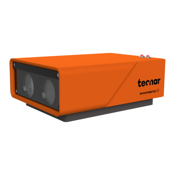
Page 13: Sensor Head
• Relative feed rate • Process Stability FIGURE 3: SENSOR HEAD (FRONT) FIGURE 4: SENSOR HEAD (BACK) This document contains information considered proprietary and confidential to Tecnar Automation Ltee 40101-00075-00 – Rev A Revision date: 2022-11-17 Page 12 of 51... - Page 14 This document contains information considered proprietary and confidential to Tecnar Automation Ltee 40101-00075-00 – Rev A Revision date: 2022-11-17 Page 13 of 51...
-
Page 15: Cables, Hoses And Antennas
Cables, hoses and antennas The Accuraspray CS is delivered with several cables, hoses, and antennas, which are described in the following table. Cables/Hoses/Antennas Description 1. IEC power cable Used to connect the Accuraspray to a power outlet. 2. Communication cable Communication between the controller and the sensor head. -
Page 16: Software Operation
Software Operation User interface overview The Accuraspray CS user interface is accessible through a web browser, but it is not actually hosted on the internet. It is streamed from the Accuraspray CS controller. Tecnar recommends using Google Chrome or Microsoft Edge (chromium based) browsers. -
Page 17: Accessing The User Interface
7. Follow the procedure in the section “Modifying Windows “hosts” file” of the “40107-00047” document. 8. You are now ready to connect to the software, please refer to the section “Connecting to the software”. This document contains information considered proprietary and confidential to Tecnar Automation Ltee 40101-00075-00 – Rev A... -
Page 18: Connecting To The Software
Another user can be viewing saved files from previous runs in the QC department. When accessing the Accuraspray CS interface, users that are not logged in are in viewer mode and can only visualize the sensor’s readings from the live screen or the strip charts screen. -
Page 19: Navigation Tabs
Navigation tabs The navigation icons are displayed on the he left of the Accuraspray CS user interface to access the different tabs. The following table describes those icons. Icons Description Access the main measurement screen (live). Access the production files screen. -
Page 20: Live Screen
Live screen The live screen displays in real time all measurements taken by the Accuraspray CS. The measurements are displayed at the top of the screen. Color codes indicate whether the measurements are within the acceptance range as defined in the setup by the process engineer. - Page 21 The different measurements provided by the Accuraspray CS are described in detail in the table below. Parameters Description 1. Velocity Average particles speed that are passing through the sensor’s measurement volume (bullseye). 2. Feed Rate Measure of the intensity reflected light by the spray plume.
-
Page 22: Selecting Active Gauges
“Active Gauges” menu. This button is also duplicated in the Clicking on the gauge button settings tab along with the other spray parameters. This document contains information considered proprietary and confidential to Tecnar Automation Ltee 40101-00075-00 – Rev A Revision date: 2022-11-17... -
Page 23: Adjusting The Time Span
When you change the min/max settings in this tab, make sure to go back to the settings tab and save your changes. FIGURE 8: PART TEMPERATURE SCREEN This document contains information considered proprietary and confidential to Tecnar Automation Ltee 40101-00075-00 – Rev A... -
Page 24: Production Reports
FIGURE 10: SAVING PRODUCTION FILE The production reports are stored on the Accuraspray CS controller’s hard drive. The directory where the files are stored is accessible by clicking on the “Open” button. It also contains all the strip charts (.csv files). The duration of the strip charts in the production report is the same as the value in the user interface when the production report was generated. -
Page 25: Setup Screen (Operator And Administrator Only)
The setup screen is where the sensor’s parameters are managed. Click the gear icon to access the setup screen. FIGURE 12: SETUP SCREEN This document contains information considered proprietary and confidential to Tecnar Automation Ltee 40101-00075-00 – Rev A Revision date: 2022-11-17 Page 24 of 51... -
Page 26: Min/Max Adjustments
Green zone Yellow zone Yellow zone Red zone Red zone FIGURE 13: GAUGES PROCESS CONTROL ZONES This document contains information considered proprietary and confidential to Tecnar Automation Ltee 40101-00075-00 – Rev A Revision date: 2022-11-17 Page 25 of 51... -
Page 27: Opening/Deleting Setups
“Delete” button. A confirmation message will appear. You will notice that the default setups cannot be deleted. FIGURE 14: OPENING/DELETING SETUPS This document contains information considered proprietary and confidential to Tecnar Automation Ltee 40101-00075-00 – Rev A Revision date: 2022-11-17... -
Page 28: Saving Setups
FIGURE 16: SAVING SETUPS Importing and exporting setups Setups can be exported from one Accuraspray CS unit and imported into another. When clicking on the “Export” button a setup file with the “setup” extension will be downloaded on your computer. -
Page 29: Setup Parameters
Setup parameters The table below explains the data acquisition parameters that are used to configure the Accuraspray CS according to the spray process you will be monitoring. See Figure 12 for additional information. Parameters Description Spray direction Particle’s travel direction (left to right or right to left) relative to the Accuraspray CS field of view. - Page 30 Changing ANY of these parameters will affect the current setup. Please make sure that you save your changes by clicking the “Save” button. This document contains information considered proprietary and confidential to Tecnar Automation Ltee 40101-00075-00 – Rev A Revision date: 2022-11-17...
-
Page 31: System Settings
A reboot is required for this operation. Refer to the document “40107-00047 – Network Connections” for in-dept details. This document contains information considered proprietary and confidential to Tecnar Automation Ltee 40101-00075-00 – Rev A Revision date: 2022-11-17... -
Page 32: Dhcp Ip
Changing the PLC IP Changing the PLC IP will change the IP of Tecnar’s PLC in the controller’s database. You must also update the IP in the PLC itself, as this only tells the controller which IP to look for when establishing the connection. Make sure that the controller, Tecnar’s PLC, and your own PLC are all on the same network/subnet. -
Page 33: Report Generation Mode
NTP server is not enabled on the controller, as it is not connected to the Internet. You may have to adjust the time zone manually to compensate for your local DST settings. This document contains information considered proprietary and confidential to Tecnar Automation Ltee 40101-00075-00 – Rev A... -
Page 34: Updating Your System
Updating your system Download the latest update archive (.7z) from Tecnar’s website and update your system gracefully with a single click. Upload the archive and click “Start Update”. Simply follow the on-screen instructions. The UI will automatically refresh once the update is finished. If not, refresh the page manually. -
Page 35: Process Stability
Additional details about the thresholds and how to set them properly are provided in the following sections. This document contains information considered proprietary and confidential to Tecnar Automation Ltee 40101-00075-00 – Rev A Revision date: 2022-11-17... -
Page 36: Overview Of The Stability Panel
�� ( �� ) = ��−µ ∗ �� − ∗( �� �� ∗ √ 2 ∗ �� This document contains information considered proprietary and confidential to Tecnar Automation Ltee 40101-00075-00 – Rev A Revision date: 2022-11-17 Page 35 of 51... -
Page 37: Figure 23: Normal Distribution
50% + 34.13% + 13.59% ≅ 97.72% Tecnar has chosen to use 2 σ as the threshold starting point for the yellow thresholds, if you decide to generate the thresholds automatically in the UI. You can always update the thresholds manually if you wish to use a different approach. -
Page 38: The Calculation Methods
You could also bypass this limitation by “aggregating” the content of the different csv files into a single file. The Accuraspray CS will then process the results as if it was one set of data. This will have the same effect as processing the files externally to find your limits. -
Page 39: Technical Specifications
40 cm (15.7 in.) Length (c) 42 cm (16.5 in.) Power requirement 100–240 VAC, 50–60 Hz, 1.5 A, auto- switch This document contains information considered proprietary and confidential to Tecnar Automation Ltee 40101-00075-00 – Rev A Revision date: 2022-11-17 Page 38 of 51... -
Page 40: Installation
5. Substrate pyrometer and its support bracket (optional) 6. Communication cable, laser power cable and safety switch cable FIGURE 24: UNPACKING THE PARTS This document contains information considered proprietary and confidential to Tecnar Automation Ltee 40101-00075-00 – Rev A Revision date: 2022-11-17... -
Page 41: Figure 25: Position Of The Sensor Head
Install the sensor head on a sturdy mounting that does not vibrate or move during spraying. Refer to the following schematics of the Accuraspray CS mounting plate. FIGURE 26: SENSOR HEAD MOUNTING PLATE DIMENSIONS. This document contains information considered proprietary and confidential to Tecnar Automation Ltee 40101-00075-00 – Rev A Revision date: 2022-11-17... -
Page 42: Figure 27: Mounting The Sensor Head
Connect the air hoses to the booth air supply. Connect the other ends of the cables to the controller as indicated on the Figure 28. This document contains information considered proprietary and confidential to Tecnar Automation Ltee 40101-00075-00 – Rev A... -
Page 43: Installing The Hmi Module
Connect the power cable to the controller and into a power socket. Flip the power switch on the controller to position ON. This document contains information considered proprietary and confidential to Tecnar Automation Ltee 40101-00075-00 – Rev A Revision date: 2022-11-17... -
Page 44: Adjusting The Spray Gun Position
Save this position as the sensor home position on the spray gun. Standard spray distance Sensor head working distance FIGURE 30: SENSOR HEAD WORKING DISTANCE. This document contains information considered proprietary and confidential to Tecnar Automation Ltee 40101-00075-00 – Rev A Revision date: 2022-11-17 Page 43 of 51... -
Page 45: Setting Up The Accuraspray On A Network (Optional)
Setting up the Accuraspray on a network (optional) To connect the Accuraspray CS to your local network you must connect the controller to the network with an Ethernet cable. Refer to the document “40107-00047 Connections” for in-depth details. Accuraspray 4.0 Network Connecting the I/Os (optional) You may remotely control the Accuraspray CS using the I/O connections. - Page 46 This document contains information considered proprietary and confidential to Tecnar Automation Ltee 40101-00075-00 – Rev A Revision date: 2022-11-17 Page 45 of 51...
-
Page 47: Maintenance
Compressed Replacing the filter Periodically (see visual air filter cartridge indicator on the cartridge cartridge assembly) This document contains information considered proprietary and confidential to Tecnar Automation Ltee 40101-00075-00 – Rev A Revision date: 2022-11-17 Page 46 of 51... -
Page 48: Maintenance Procedures
Put the new assembly on the sensor with the air knife at the top (facing downward). Insert the four M3 screws to secure the plate. This document contains information considered proprietary and confidential to Tecnar Automation Ltee 40101-00075-00 – Rev A... -
Page 49: Recommended Spare Parts
Calibrating the sensor head All sensor heads are calibrated at Tecnar before being shipped to the end-users. To ensure accurate measurements, sensor calibration should be verified every year to maintain the repeatability of the measurements. You must send the sensor heads to Tecnar Automation Ltd every year for calibration, contact service@tecnar.com. -
Page 50: Troubleshooting
3 blinks Internal micro-switch error Contact Tecnar service team 4 blinks Microcontroller error Contact Tecnar service team This document contains information considered proprietary and confidential to Tecnar Automation Ltee 40101-00075-00 – Rev A Revision date: 2022-11-17 Page 49 of 51... -
Page 51: Error Reporting In The User Interface
Invalid measurements (Saturated The proper setup has been selected. signal) • EXPOSURE TIME is set adequately for your process. This document contains information considered proprietary and confidential to Tecnar Automation Ltee 40101-00075-00 – Rev A Revision date: 2022-11-17 Page 50 of 51... -
Page 52: Service & Support
Should you have any questions concerning our equipment, please contact us at: TECNAR Automation 1321, Hocquart Street St-Bruno, Qc, Canada, J3V 6B5 Phone: 450-461-1221 Fax: 450-461-0808 Email: service@tecnar.com This document contains information considered proprietary and confidential to Tecnar Automation Ltee 40101-00075-00 – Rev A Revision date: 2022-11-17 Page 51 of 51...
Need help?
Do you have a question about the Accuraspray CS and is the answer not in the manual?
Questions and answers