Table of Contents
Advertisement
Quick Links
Advertisement
Table of Contents

Related Manuals for Vantron VT-SBC-3588


Summary of Contents for Vantron VT-SBC-3588
- Page 1 Vantron | Embedded in your success, Embedded in your better life World-leading provider of embedded/IoT products and solutions VT-SBC-3588 Single Board Computer User Manual Version: 1.2 © Vantron Technology, Inc. All rights reserved. VT-SBC-3588 | User Manual www.vantrontech.com...
- Page 2 Vantron | Embedded in your success, Embedded in your better life World-leading provider of embedded/IoT products and solutions Revision History Version Description Date V1.0 First release Jun 14, 2022 V1.1 Updated pinout description of certain connectors Aug 30, 2022 V1.2...
-
Page 3: Table Of Contents
Vantron | Embedded in your success, Embedded in your better life World-leading provider of embedded/IoT products and solutions Table of Contents Foreword ............................1 CHAPTER 1 INTRODUCTION ......................5 Product Overview ......................6 Terminology ........................6 Block Diagram ........................7 Specifications ........................ - Page 4 Vantron | Embedded in your success, Embedded in your better life World-leading provider of embedded/IoT products and solutions 2.4.30 J29 Micro SIM slot (30) ....................30 2.4.31 J3 Micro SD slot (31) ....................... 30 CHAPTER 3 FIRST-USE DEBUGGING ....................31 Serial connectors ......................
-
Page 5: Foreword
Under no circumstances shall any part of this user manual be copied, reproduced, translated, or sold. This manual is not intended to be altered or used for other purposes unless otherwise permitted in writing by Vantron. Vantron reserves the right of all publicly released copies of this manual. - Page 6 Email: sales@vantrontech.com Symbology This manual uses the following signs to prompt users to pay special attention to relevant information. Caution for latent damage to system or harm to personnel Attention to important information or regulations VT-SBC-3588 | User Manual www.vantrontech.com...
- Page 7 The use or placement of the operation tools shall comply with the code of practice of such tools to avoid short circuit of the Product. Cut off the power before inspection of the Product to avoid human injury or product • damage. VT-SBC-3588 | User Manual www.vantrontech.com...
- Page 8 Clean with a damp cloth • Do not try to clean exposed electronic components unless with a dust collector Power off and contact Vantron technical support engineer in case of the following faults: The Product is damaged • The temperature is excessively high •...
-
Page 9: Chapter 1 Introduction
Vantron | Embedded in your success, Embedded in your better life World-leading provider of embedded/IoT products and solutions CHAPTER 1 INTRODUCTION VT-SBC-3588 | User Manual www.vantrontech.com... -
Page 10: Product Overview
World-leading provider of embedded/IoT products and solutions 1.1 Product Overview Vantron VT-SBC-3588 Single Board Computer is powered by Rockchip latest flagship RK3588 AIoT chipset that is equipped with an 8-core 64-bit CPU, an ARM Mali-G610 MP4 quad-core GPU, and a built-in AI acceleration NPU, capable of providing 6 TOPS computing power and supporting mainstream deep learning frameworks. -
Page 11: Block Diagram
Vantron | Embedded in your success, Embedded in your better life World-leading provider of embedded/IoT products and solutions 1.3 Block Diagram VT-SBC-3588 | User Manual www.vantrontech.com... -
Page 12: Specifications
BlueSphere OTA Power Input 12V/5A, 24V/3A 1 x Power terminal Mechanical Dimensions 146.94mm x 140mm x 24.34mm Temperature Operating: 0℃ ~ +60℃ Storage: -40℃ ~ +85℃ Environment Humidity RH 0~95% (non-condensing) condition Certification FCC, CCC VT-SBC-3588 | User Manual www.vantrontech.com... -
Page 13: Operating System
1.8 Environmental Specifications VT-SBC-3588 works at a temperature ranging from 0℃ to +60℃ and at relative humidity of no more than RH 96% for non-condensing purpose. It is designed to be stored at a temperature ranging from -40°C to +85°C. -
Page 14: Chapter 2 Connector Description
Vantron | Embedded in your success, Embedded in your better life World-leading provider of embedded/IoT products and solutions CHAPTER 2 CONNECTOR DESCRIPTION VT-SBC-3588 | User Manual www.vantrontech.com... -
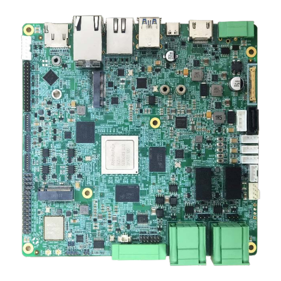
Page 15: Product Layout
8GB LPDDR4 RAM by default, and users also have the option of 16GB RAM. 2.2.2 eMMC flash The VT-SBC-3588 provides an eMMC 5.1 flash up to 128 GB, and the default capacity is 32GB. It is used as the default boot and storage device. 2.2.3 Storage expansion The VT-SBC-3588 implements a Micro SD slot for expansion of the storage capacity. -
Page 16: Identification Of Pin 1
This section is going to brief on the connectors/jumpers on the Board with corresponsive pinout description. 2.4.1 J1 Power terminal (1) VT-SBC-3588 supports 12V/24V DC power input (12V 5A recommended) and implements a 3-pin power terminal (1 x 3 x 3.81mm) to supply power for the Board. Pin 1... -
Page 17: J22 Ethernet Jack (2)
The VT-SBC-3588 offers two USB 3.0 Type-A interfaces for connecting peripherals. The maximum output of each interface is 5V/1A. 2.4.5 J6 USB Type-C (5) VT-SBC-3588 implements a USB Type-C interface, supporting USB 3.0 OTG and DP 1.4 video output, with a maximum output of 5V/1.5A. VT-SBC-3588 | User Manual... -
Page 18: J7/J8/J9 Usb 2.0 Host Connectors (6)
World-leading provider of embedded/IoT products and solutions 2.4.6 J7/J8/J9 USB 2.0 Host connectors (6) The VT-SBC-3588 has three on-board USB 2.0 connectors (1 x 4 x 2.0mm) set in the host mode by default. The maximum output of each connector is 5V/0.5A. -
Page 19: J13 Lvds (7)
World-leading provider of embedded/IoT products and solutions 2.4.7 J13 LVDS (7) The VT-SBC-3588 offers a dual-channel LVDS to connect high-definition displays (resolution up to 1920 x 1080 @60Hz). It is recommended that you use LVDS shielded twisted pairs to connect the interface for improved transmission reliability. -
Page 20: J15 Backlight Connector (8)
4096 x 2160 @60Hz, and it supports HDMI 2.1 protocol. 2.4.10 J17 eDP (10) The VT-SBC-3588 implements an eDP interface (1 x 30 x 0.5mm) for image output with a resolution up to 4096 x 2160 @60Hz, and it supports HDMI 2.1 protocol. It is recommended that you use LVDS shielded twisted pairs to connect the interface for improved transmission reliability. - Page 21 LCD backlight control output, LCD_BL_EN_H 3.3V level LCD backlight brightness control LCD_BL_PWM1 output, 3.3V level Ground Ground Ground VCC12V_LCD_EDP 12V backlight power output VCC12V_LCD_EDP 12V backlight power output VCC12V_LCD_EDP 12V backlight power output VCC12V_LCD_EDP 12V backlight power output VT-SBC-3588 | User Manual www.vantrontech.com...
-
Page 22: J16 Mipi Dsi (11)
| Embedded in your success, Embedded in your better life World-leading provider of embedded/IoT products and solutions 2.4.11 J16 MIPI DSI (11) The VT-SBC-3588 implements a MIPI DSI connector (1 x 31 x 0.3mm) for connecting displays, supporting a resolution up to 1920 x 1080 @60Hz. Pin 1... -
Page 23: J10/J11 Mipi Csi (12)
VCC3V3_LCD 3.3V power output VCC3V3_LCD 3.3V power output 2.4.12 J10/J11 MIPI CSI (12) The VT-SBC-3588 has two MIPI CSI connectors (1 x 31 x 0.3mm) for connecting cameras. Pin 1 Pin 1 Pinout description of J10 (CAM 1): Name Type... - Page 24 CAM2 master clock output, voltage MIPI_CAM2_MCLK domain 1.8V Ground VCC_1V8_CAM2 1.8V power output VCC_1V8_CAM2 1.8V power output 1.2V power output, voltage level VCC_1V2_CAM2 adjustment supported by hardware VCC_2V8_AF_CAM2 2.8V motor power output VCC_2V8_CAM2 2.8V power output VT-SBC-3588 | User Manual www.vantrontech.com...
-
Page 25: J28 M.2 B-Key (13)
Ground 2.4.13 J28 M.2 B-Key (13) The VT-SBC-3588 offers an M.2 B-Key socket that supports a size of 2242. It is compatible with the SATA 3.0 bus. You can connect an SSD for huge data transfer and storage, but please note that it's not available simultaneously with the SATA signal of port J26. - Page 26 Pinout description of JP3: Name Type Description 485_B_3 RS485_3 B, 120Ω resistor connection in series 485_A_3 RS48_3 A Pinout description of JP3: Name Type Description 485_B_4 RS485_4 B, 120Ω resistor connection in series 485_A_4 RS48_4 A VT-SBC-3588 | User Manual www.vantrontech.com...
-
Page 27: J34 Rs232/Rs485 (Phoenix Terminal) (16)
World-leading provider of embedded/IoT products and solutions 2.4.16 J34 RS232/RS485 (Phoenix terminal) (16) The VT-SBC-3588 implements a 6-pin Phoenix terminal (2 x 3 x 3.81mm) configured as two isolated RS232/RS485 multiplex connectors (UART 4 and UART 7). The two connectors are identified as /dev/ttyS7 and /dev/ttyS4 in the software system. -
Page 28: J32 Can (17)
RS485_B_2 RS485_2 B, 120Ω resistor connection in series RS485_A_2 RS485_2 A 2.4.17 J32 CAN (17) The VT-SBC-3588 also implements another 6-pin Phoenix terminal (2 x 3 x 3.81mm) configured as two CAN connectors. Pin 1 Pin 4 Pinout description: Name... -
Page 29: J39 Spi (18)
SPI CS, 3.3V level VCC_3V3_S0 3.3V power output Ground 2.4.19 J37 GPIO (Phoenix terminal) (19) The VT-SBC-3588 offers 4 GPIOs on a 6-pin Phoenix terminal (1 x 6 x 3.81mm) to users to connect and control external devices. Pin 1 Pinout description: Name... -
Page 30: J38 Gpio Header (20)
GPIO 5V level GPIO2_5V GPIO 5V level 5V power output VCC_5V0 Ground 2.4.21 J24 Microphone connector (21) The VT-SBC-3588 provides a microphone connector (1 x 2 x 2mm) for the audio input. Pin 1 Pinout description: Name Type Description MIC2P... -
Page 31: J23 Line Out Connector (22)
The RTC battery connector is designed to connect a battery to power the RTC and ensure accurate timekeeping . A 3V RTC battery is recommended. Pin 1 Pinout description: Name Type Description RTC_P RTC power input, 3V Ground VT-SBC-3588 | User Manual www.vantrontech.com... -
Page 32: J31 Debug Port (25)
Board. It is recommended to connect a fan with power consumption less than 6W (12V/0.5A). Pin 1 Pinout description: Name Type Description Ground FAN_12V 12V power output, current limit 0.5A PWM0_M2_FAN PWM output, voltage domain 5V VT-SBC-3588 | User Manual www.vantrontech.com... -
Page 33: J14 Power Button Connector (27)
If the SATA signal of this interface is utilized for connecting an SSD, then the M.2 B-Key socket’s SATA signal will not be available. Conversely, if the M.2 B-Key socket’s SATA signal is utilized, then the SATA 3.0 interface will be disabled. VT-SBC-3588 | User Manual www.vantrontech.com... -
Page 34: J27 Sata Power Connector (29)
There is a Micro SIM slot on the back of the VT-SBC-3588. Specifications: Micro SIM, push-push, hot plug supported 2.4.31 J3 Micro SD slot (31) The VT-SBC-3588 implements a Micro SD slot for expansion of the storage capacity, supporting up to 128GB storage. VT-SBC-3588 | User Manual... -
Page 35: Chapter 3 First-Use Debugging
Vantron | Embedded in your success, Embedded in your better life World-leading provider of embedded/IoT products and solutions CHAPTER 3 FIRST-USE DEBUGGING VT-SBC-3588 | User Manual www.vantrontech.com... -
Page 36: Serial Connectors
This chapter is mainly about the first-use debugging of interfaces and software applications. You can connect a key board, a mouse and a display to the VT-SBC-3588 and debug the Board directly in the console, or, you can use a USB Type-A to Type-C cable to connect the Board to a host computer for remote debugging. - Page 37 # echo "Test string" > /dev/ttyS4 3. Open another terminal and use UART7 to receive data; # gpioset gpiochip7 6=0 # gpioset gpiochip7 7=1 # cat /dev/ttyS7 4. The results will be printed as shown above. VT-SBC-3588 | User Manual www.vantrontech.com...
- Page 38 # gpioset gpiochip7 7=1 # cat /dev/ttyS7 # gpioset gpiochip6 1=0 Transmit data # gpioset gpiochip6 0=1 # echo "Test string" > /dev/ttyS8 UART 8 # gpioset gpiochip6 1=0 Receive data # gpioset gpiochip6 0=1 # cat /dev/ttyS8 VT-SBC-3588 | User Manual www.vantrontech.com...
- Page 39 # gpioset gpiochip7 7=0 # cat /dev/ttyS7 # gpioset gpiochip6 1=1 Transmit data # gpioset gpiochip6 0=0 # echo "Test string" > /dev/ttyS8 UART 8 # gpioset gpiochip6 1=1 Receive data # gpioset gpiochip6 0=0 # cat /dev/ttyS8 VT-SBC-3588 | User Manual www.vantrontech.com...
-
Page 40: Can
World-leading provider of embedded/IoT products and solutions 3.2 CAN The VT-SBC-3588 implements two CAN bus connectors (CAN0 and CAN1). To test data transmitting and receiving of the connectors, input the following commands in the terminal to check if the connectors can write and read data:... -
Page 41: Gpio
World-leading provider of embedded/IoT products and solutions 3.3 GPIO The VT-SBC-3588 offers 7 GPIOs (see details in 2.4.19~2.4.20). You can set the high/low level of the GPIO pins and use a voltmeter to check if the settings are valid. Input the following commands in the terminal to check the status of the GPIOs:... - Page 42 # gpioset gpiochip8 5=1 GPIO6 Low level # gpioset gpiochip8 5=0 High level # gpioset gpiochip8 6=1 GPIO7 Low level # gpioset gpiochip8 6=0 High level # gpioset gpiochip8 7=1 GPIO8 Low level # gpioset gpiochip8 7=0 VT-SBC-3588 | User Manual www.vantrontech.com...
-
Page 43: Watchdog Timer
2. Set the Runtime for dog feeding (e.g., 22 seconds) and the interval for system reboot upon an abnormality (e.g., 2 minutes); echo V > /dev/watchdog 3. Disable the watchdog; # echo V > /dev/watchdog 4. Users can also enable hardware watchdog in “systemd” and configure it likewise. # /etc/systemd/system.conf VT-SBC-3588 | User Manual www.vantrontech.com... -
Page 44: Chapter 4 Android System Manual
Vantron | Embedded in your success, Embedded in your better life World-leading provider of embedded/IoT products and solutions CHAPTER 4 ANDROID SYSTEM MANUAL VT-SBC-3588 | User Manual www.vantrontech.com... -
Page 45: Enable Developer Options
4.1 Enable Developer Options To enable Developer options of the VT-SBC-3588, follow the steps below: 1. Connect the VT-SBC-3588 to a mouse, a keyboard, and a display for easier operations; 2. Click Settings > About tablet in sequence; 3. Scroll down to Build number, and click it consecutively for at least 7 times to enable Developer options;... - Page 46 4. Press “Win + R” and input “sysdm.cpl” in the dialogue box to open the settings interface; 5. Click in sequence Advanced > Environment Variables > Path > Edit, and click New in the pop-up; 6. Copy the folder path of adb.exe, and click OK to confirm; VT-SBC-3588 | User Manual www.vantrontech.com...
-
Page 47: App Installation Via Adb Commands
The Windows environment is used for illustration in the following section. 4.3.1 Prerequisites • The VT-SBC-3588 running Android operating system A host computer running Windows 7 or later (Ubuntu 18.04 or later recommended • for Ubuntu environment) A USB cable (Type-A to Type-C) •... -
Page 48: Image Flashing On A Windows Host
<App path> you typed in manually. 4.4 Image Flashing on a Windows Host Whenever a new image is available, Vantron will provide a release package consisting of all the tools/files necessary so that you can flash the image as needed. - Page 49 5. A pop-up will appear in a second suggesting the driver is installed; 6. Open the directory of the upgrade tool (path: \ SW \AndroidTool \RKDevTool_Release_ vxxx \ RKDevTool); 7. Double click the program to install the RKDevTool.exe; VT-SBC-3588 | User Manual www.vantrontech.com...
- Page 50 World-leading provider of embedded/IoT products and solutions 8. Open the upgrade window; 9. Connect the VT-SBC-3588 to the Windows host with the USB Type-A to Type-C cable; 10. Press Windows key + R and input “cmd” in the dialog box to open the command prompt;...
-
Page 51: Image Flashing
2. Open the image file update.img from the directory (\ SW \ Image), and the firmware details will be automatically populated; 3. Click Upgrade button (next to Firmware button), and the device will start to download the image and upgrade; 4. When the upgrade finishes, the Device will reboot automatically. VT-SBC-3588 | User Manual www.vantrontech.com... -
Page 52: Chapter 5 Debian System Manual
Vantron | Embedded in your success, Embedded in your better life World-leading provider of embedded/IoT products and solutions CHAPTER 5 DEBIAN SYSTEM MANUAL VT-SBC-3588 | User Manual www.vantrontech.com... -
Page 53: About The System
3. Right click the mouse in an empty area to open the property dialogue of the Device; 4. Click Applications > About Xface to enter the desktop environment, then you can check the system information like device name, operating system, copyright statement, etc. VT-SBC-3588 | User Manual www.vantrontech.com... -
Page 54: System Settings
° Switch between different workspaces. Other system settings are accessible from Applications on the top left corner of the screen or upon a right click of the mouse in an empty area of the screen. VT-SBC-3588 | User Manual www.vantrontech.com... -
Page 55: Language Setup
(en_US.UTF-8 for instance) to select the language, and press “Space” in front of the current locale (zh_CN.UTF-8) to uncheck the current language, then press “Tab” to move the cursor to the left option (Yes) and “Enter” to confirm your choice; VT-SBC-3588 | User Manual www.vantrontech.com... - Page 56 “Enter” to confirm your choice; 7. Wait a few seconds for the locale to take effect; 8. Input “reboot” to restart the system and use “locale -a” to check if the locale is set as default. VT-SBC-3588 | User Manual www.vantrontech.com...
-
Page 57: Time And Date Setup
3. Click Time zone and select your own time zone from the list; 4. Choose to synchronize the time with the Internet server or fill in the time manually; 5. Click Lock to let the settings take effect. VT-SBC-3588 | User Manual www.vantrontech.com... -
Page 58: Network Configuration
Connection Information: 3. To edit the network configurations, you can right click the network icon and select Edit Connections, then select a connection point and click the cog icon to edit the network settings. VT-SBC-3588 | User Manual www.vantrontech.com... -
Page 59: Image Flashing On An Ubuntu Host
4. Run “adb shell” to execute shell commands on the Device; 5. Enter “reboot loader”, and the Device will reboot automatically and enter the loader mode; 6. Copy the image package provided by Vantron to the Ubuntu host (for instance, in the Documents folder);... - Page 60 9. Input the password for the user of the Ubuntu host to download the system image; 10. The system will start upgrading once the download finishes, and the Device will reboot automatically when the upgrade finishes. VT-SBC-3588 | User Manual www.vantrontech.com...
-
Page 61: Chapter 6 Ubuntu System Manual
Vantron | Embedded in your success, Embedded in your better life World-leading provider of embedded/IoT products and solutions CHAPTER 6 UBUNTU SYSTEM MANUAL VT-SBC-3588 | User Manual www.vantrontech.com... -
Page 62: About The System
1. Connect the Device with a monitor using an HDMI cable, or using an HDMI to VGA adapter if necessary; 2. Power on the Device and input the password to login the default user (“vantron”); Password: 123456 3. Click the Show Applications icon on the bottom left corner to access the system applications;... -
Page 63: System Settings
You can input the following command to check the information of the network interface: ip link show. 6.2.4 User Users will be able to edit the system account and add/delete a user after inputting the password and unlocking the current user. VT-SBC-3588 | User Manual www.vantrontech.com... -
Page 64: Image Flashing On An Ubuntu Host
4. Run “adb shell” to execute shell commands on the Device; 5. Enter “reboot loader”, and the Device will reboot automatically and enter the loader mode; 6. Copy the image package provided by Vantron to the Ubuntu host (for instance, in the Documents folder); VT-SBC-3588 | User Manual... -
Page 65: Ros Tutorials
9. Input the sudo password to download the system image; 10. The system will start upgrading once the download finishes, and the Device will reboot automatically when the upgrade finishes. 6.4 ROS Tutorials Please refer to http://wiki.ros.org/ROS/Tutorials for the details of the ROS system. VT-SBC-3588 | User Manual www.vantrontech.com... -
Page 66: Chapter 7 Disposal And Warranty
Vantron | Embedded in your success, Embedded in your better life World-leading provider of embedded/IoT products and solutions CHAPTER 7 DISPOSAL AND WARRANTY VT-SBC-3588 | User Manual www.vantrontech.com... -
Page 67: Disposal
& electronic waste recycling/disposal center. Proper disposal of this sort of waste helps avoid harm and adverse effect upon surroundings and people’s health. Please contact local organizations or recycling/disposal center for more recycling/disposal methods of related products. VT-SBC-3588 | User Manual www.vantrontech.com... -
Page 68: Warranty
CUSTOMER’s location and no Product so inspected shall be returned to VANTRON unless the cause for the rejection or defect is determined to be the responsibility of VANTRON. VANTRON shall in turn provide the CUSTOMER turnaround shipment on defective Product within fourteen (14) working days upon its receipt at VANTRON.
Need help?
Do you have a question about the VT-SBC-3588 and is the answer not in the manual?
Questions and answers