Table of Contents
Advertisement
Quick Links
Advertisement
Table of Contents

Related Manuals for National Instruments NI 9505


Summary of Contents for National Instruments NI 9505
- Page 1 NI-9505...
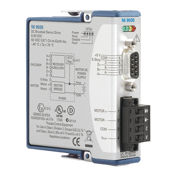
- Page 2 OPERATING INSTRUCTIONS AND SPECIFICATIONS NI 9505E DC Brushed Servo Drive...
- Page 3 C Series documentation. Caution National Instruments makes no electromagnetic compatibility (EMC) or CE marking compliance claims for the NI 9505E. The end-product supplier is responsible for conformity to any and all compliance requirements. Caution The NI 9505E must be installed inside a suitable enclosure prior to use.
- Page 4 NI 9505E Dimensions The following figure shows the dimensions of the NI 9505E. 73.4 (2.89) 0.0 (0.00) Figure 1. NI 9505E Dimensions in Millimeters (Inches) © National Instruments Corp. NI 9505E Operating Instructions and Specifications...
- Page 5 The NI 9505E also returns status information such as drive fault status, V presence, and emergency stop status to the LabVIEW FPGA Module for use in system monitoring. Refer to the NI 9505 Reference Help book in the LabVIEW Help, ni.com NI 9505E Operating Instructions and Specifications...
- Page 6 Refer to the labview\ directory examples\CompactRIO\Module Specific\NI 9505 for example VIs using the NI 9505E and NI SoftMotion. © National Instruments Corp. NI 9505E Operating Instructions and Specifications...
- Page 7 LabVIEW FPGA Module NI 9505E Position Fault Fault Setpoint Detection Monitor Motor Velocity Current (PWM) Command Command* Velocity Current Position Bridge H-Bridge Servo Loop Loop Loop Controller Motor Position Velocity Current Feedback Feedback Feedback Velocity Estimator Current Sense Encoder Feedback Position Encoder Decoder...
- Page 8 LabVIEW FPGA Module Acceleration Velocity Position Error Current Command Position (Proportional to Torque) Setpoint Position Feedback Encoder Feedback Position Decoder Figure 3. LabVIEW FPGA Module NI 9505E PID Loop © National Instruments Corp. NI 9505E Operating Instructions and Specifications...
- Page 9 You can enable the regardless of whether V drive using the Enable Drive method in software. Refer to the NI 9505 Reference Help book in the LabVIEW Help, available by selecting Help»Search the LabVIEW Help, for more information about enabling the drive.
-
Page 10: Led Indicators
The Power LED (green) illuminates when the NI 9505E is properly inserted into a powered chassis. Note The Power LED does not illuminate when the chassis is in sleep mode. © National Instruments Corp. NI 9505E Operating Instructions and Specifications... - Page 11 The drive is disabled by default at power-on. You can enable the drive using the Enable Drive method in software. Refer to the NI 9505 Reference Help book in the LabVIEW Help, available by selecting Help»Search the LabVIEW Help, for more information about this method.
-
Page 12: Sleep Mode
Typically, when a system is in sleep mode, you cannot communicate with the modules. In sleep mode, the system consumes minimal power and may dissipate less heat than it does © National Instruments Corp. NI 9505E Operating Instructions and Specifications... - Page 13 in normal mode. Refer to the Specifications section for more information about power consumption and thermal dissipation. The Power LED does not illuminate when the Note chassis is in sleep mode. Wiring the NI 9505E The NI 9505E has a 9-pin female DSUB connector that provides connections for the encoder inputs, a +5 V connection for encoder power, a connection for an emergency stop input, and a connection to COM.
- Page 14 Encoder Index– (Phase Z–) Common (COM) Table 2. NI 9505E Screw-Terminal Terminal Assignments Module Terminal Signal MOTOR+ M– MOTOR– M– COM (motor DC power supply reference) (motor DC power supply) © National Instruments Corp. NI 9505E Operating Instructions and Specifications...
- Page 15 Figure 5 shows a typical NI 9505E connection example, including encoder and E-Stop inputs. Shield Phase A± Encoder Phase B± Feedback Index± +5 V +24 V E-Stop Shield Motor M– Shield Motor DC Power Supply NI 9505E Figure 5. NI 9505E Connections ni.com NI 9505E Operating Instructions and Specifications...
- Page 16 85 ºC. The NI 9931 is available from (NI part number 780571-01) or by calling ni.com your National Instruments sales representative. Refer to the section for more information. Refer to Figure 6 for Specifications an illustration.
- Page 17 Motor Power Signals The MOTOR+ and MOTOR– signals power the servo motor. Motor direction is as follows: • Forward—Clockwise (CW) facing motor shaft • Reverse—Counterclockwise (CCW) facing motor shaft Figure 7 shows clockwise and counterclockwise motor rotation. Figure 7. Clockwise and Counterclockwise Motor Rotation If the motor does not turn in the desired direction, reverse the MOTOR+ and MOTOR–...
-
Page 18: Encoder Signals
Refer to the examples installed at labview\examples\ for examples of using CompactRIO\Module Specific\NI 9505 the encoder signals. Refer to the NI 9505 Reference Help book in the LabVIEW Help, available by selecting Help»Search the LabVIEW Help, for more information. © National Instruments Corp. - Page 19 If the encoder cable length is greater than 3.05 m (10 ft), use encoders with differential line driver outputs for your applications. Power for a +5 V encoder—generated by a power supply on the NI 9505E—is available on pin 5 of the DSUB connector. Encoder NI 9505E +5 V...
- Page 20 Refer to Figure 7 for a depiction of clockwise and counterclockwise rotation. If encoder counting does not behave as expected, change the encoder polarity in the FPGA or swap the Phase A and Phase B connections. © National Instruments Corp. NI 9505E Operating Instructions and Specifications...
-
Page 21: Emergency Stop Signal
The E-Stop functionality is disabled by default. Refer to the NI 9505 Reference Help book in the LabVIEW Help, available by selecting Help»... - Page 22 • Tie the V cable shield to chassis ground at the module side only. • Tie the motor cable shield to chassis ground at the motor side only. © National Instruments Corp. NI 9505E Operating Instructions and Specifications...
- Page 23 • Tie the encoder cable shield to COM at the encoder side only. • Wire encoder signals and their ground connections separately from all other connections to prevent lost encoder counts. • Route wires along the machine frame to reduce high frequency noise.
-
Page 24: Specifications
........12 A < 2 s max For more information about maximum continuous current at temperatures less than 85 ºC, visit and enter ni.com/info rdmot2 Allow at least 3.4 s between peak current intervals. © National Instruments Corp. NI 9505E Operating Instructions and Specifications... - Page 25 Rate..........20 kHz recommended, 40 kHz max Violating minimum pulse width will result Caution in unpredictable performance. Minimum pulse width (high or low)....... 2 µs Drive direction update rate ....Nominally 20 µs Current loop ADC resolution ......12 bits Current range......
- Page 26 Temperature fault trip point ....115 ºC (module temperature) Encoder Input Characteristics Number of inputs ......3 Input type .......... Differential or single-ended Voltage range ........0 to 5.5 VDC © National Instruments Corp. NI 9505E Operating Instructions and Specifications...
- Page 27 Digital logic levels Single-ended....... TTL compatible Input high threshold ..... 2.4 V Input low threshold ....0.8 V Differential Input threshold ..... ±700 mV, line driver compatible Common-mode voltage..–7 to 12 V Input current ....... ±1 mA Maximum quadrature frequency..5 MHz E-Stop Input Input voltage range ......
-
Page 28: Power Requirements
Note For two-dimensional drawings and three-dimensional models of the C Series module and connectors, visit and search by module number. ni.com/dimensions © National Instruments Corp. NI 9505E Operating Instructions and Specifications... - Page 29 Screw-terminal wiring ...... 12 to 24 AWG copper conductor wire with 10 mm (0.39 in.) of insulation stripped from the end Torque for screw-terminals ....0.5 to 0.6 N · m (4.4 to 5.3 lb · in.) Ferrules ..........0.25 mm to 2.5 mm Weight (without screw-terminal) ..
- Page 30 This category is for measurements of voltages from specially protected secondary circuits. Such voltage measurements include signal levels, special equipment, limited-energy parts of equipment, circuits powered by regulated low-voltage sources, and electronics. © National Instruments Corp. NI 9505E Operating Instructions and Specifications...
-
Page 31: Safety Standards
, search by module number or product line, and certification click the appropriate link in the Certification column. Environmental National Instruments C Series modules are intended for indoor use only, but may be used outdoors if installed in a suitable enclosure. ni.com NI 9505E Operating Instructions and Specifications... -
Page 32: Environmental Management
Maximum altitude......2,000 m Pollution Degree ....... 2 Environmental Management National Instruments is committed to designing and manufacturing products in an environmentally responsible manner. NI recognizes that eliminating certain hazardous substances from our products is beneficial to the environment and to NI customers. - Page 33 EU Customers must be sent to a WEEE recycling center. For more information about WEEE recycling centers and National Instruments WEEE initiatives, visit ni.com/ environment/weee National Instruments (RoHS) National Instruments RoHS (For information ni.com/environment/rohs_china about China RoHS compliance, go to ni.com/...
-
Page 34: Where To Go For Support
Where to Go for Support The National Instruments Web site is your complete resource for technical support. At you have access to ni.com/support everything from troubleshooting and application development self-help resources to email and phone assistance from NI Application Engineers. - Page 35 For patents covering National Instruments products/technology, refer to the appropriate location: Help»Patents in your software, the patents.txt file on your media, or the National Instruments Patent Notice at ni.com/patents .
Need help?
Do you have a question about the NI 9505 and is the answer not in the manual?
Questions and answers