Fujitsu AIRSTAGE ARUM24TLAV Installation Manual
Hide thumbs
Also See for AIRSTAGE ARUM24TLAV:
- Service manual (247 pages) ,
- Design & technical manual (978 pages) ,
- Operating manual (5 pages)
Table of Contents
Advertisement
Quick Links
INSTALLATION MANUAL
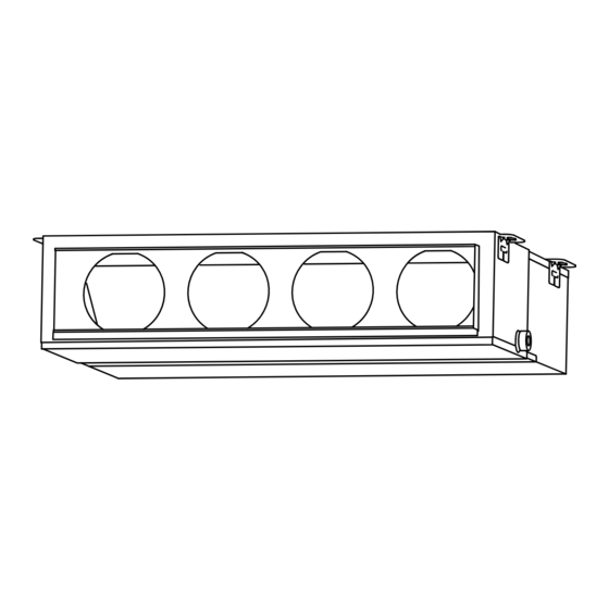
INDOOR UNIT (Duct type)
For authorized service personnel only.
MANUEL D'INSTALLATION
APPAREIL INTÉRIEUR (type conduit)
Pour le personnel agréé uniquement.
MANUAL DE INSTALACIÓN
UNIDAD INTERIOR (Tipo conducto)
Únicamente para personal de servicio autorizado.
ARUM24TLAV
ARUM30TLAV
ARUM36TLAV
PART NO. 9373385172-03
Advertisement
Table of Contents

Related Manuals for Fujitsu AIRSTAGE ARUM24TLAV


Summary of Contents for Fujitsu AIRSTAGE ARUM24TLAV
- Page 1 INSTALLATION MANUAL INDOOR UNIT (Duct type) For authorized service personnel only. MANUEL D’INSTALLATION APPAREIL INTÉRIEUR (type conduit) Pour le personnel agréé uniquement. MANUAL DE INSTALACIÓN UNIDAD INTERIOR (Tipo conducto) Únicamente para personal de servicio autorizado. ARUM24TLAV ARUM30TLAV ARUM36TLAV PART NO. 9373385172-03...
-
Page 2: Table Of Contents
INSTALLATION MANUAL If Necessary, Get Help These instructions are all you need for most installation sites and maintenance conditions. PART NO. 9373385172-03 If you require help for a special problem, contact our sales/service outlet or your certifi ed VRF system indoor unit (Duct type) dealer for additional instructions. -
Page 3: About This Product
• Be sure to read this Manual thoroughly before installation. 2.3. Accessories • The warnings and precautions indicated in this Manual contain important information pertaining to your safety. Be sure to observe them. • Hand this Manual, together with the Operating Manual to the customer. WARNING Request the customer to keep them on hand for future use, such as for relocating or repairing the unit. -
Page 4: Optional Parts
2.5. About unit of the length "All Fujitsu General products are manufactured to metric units and tolerances. United States customary units are provided for reference only. In cases where exact dimensions and tolerances are required, always refer to metric units."... -
Page 5: Installation Dimensions
3.3.1. Installing the hangers 3.2. Installation dimensions Hanging bolt installation diagram. • Provide the space around the unit as shown in the following fi gure. (Top side) Unit: in. (mm) 29-1/8 (740) 18-3/4 (477) 6 (150) or more 16 (400) or more 1 16 in. - Page 6 Base horizontal direction leveling on top of the unit. • The screw holes to install the fl ange are located behind the round cutouts in the insula- tion. Drain hose Give a slight tilt to the side to which the drain hose is connected. The tilt should be in the range of 0 to 0.19 in.
-
Page 7: Pipe Installation
(4) Seal with a band and vinyl tape, etc. so that air does not leak from the connection. 4.3. Flare connection (pipe connection) WARNING Tighten the flare nuts with a torque wrench using the specified tightening method. Otherwise, the fl are nuts could break after a prolonged period, causing refrigerant to leak and generate hazardous gas if the refrigerant comes into contact with a fl... -
Page 8: Installing Heat Insulation
Tighten with 2 wrenches. (Left side) Unit: in. (mm) Holding wrench 9-7/16 (240) Flare nut Torque wrench Indoor unit pipe Connection pipe (Body side) Flare nut [in. (mm)] Tightening torque [lbf·ft. (N·m)] 1/4 (6.35) dia. 11.8 to 13.3 (16 to 18) Drain port 3/8 (9.52) dia. -
Page 9: Electrical Wiring
Wrap the Drain hose insulation around the drain hose connection. 6. ELECTRICAL WIRING Drain hose insulation WARNING (Accessories) Electrical work must be performed in accordance with this Manual by a person certifi ed under the national or regional regulations. Be sure to use a dedicated circuit for the Drain pan unit. -
Page 10: Electrical Requirement
(Crossover wiring of power supply) 6.1. Electrical requirement Indoor unit Indoor unit Indoor unit Power supply Power supply Power supply Voltage rating 208 / 230 V Operating range 187 to 253 V • Select the power cable type and size in accordance with relevant local and national regulations. -
Page 11: Connection Of Wiring
Strip 3/8 in. 6.4. Connection of wiring Ring terminal (10 mm) (1) Remove the control box cover and install each connection cable. Sleeve Screw with special Screw with washer special washer Cable Ring terminal Ring terminal Terminal block Cable WARNING Use ring terminals and tighten the terminal screws to the specifi... -
Page 12: External Input And External Output (Optional Parts)
• Fix the conduit with the supporters as shown below. Do not impress a voltage exceeding 24V across pins 1-2, and 1-3. *a The allowable current is DC 5mA to 10mA. (Recommended: DC5mA) Conduit (Power supply cable) Provide a load resistance such that the current becomes DC10mA or less. Supporter Select very low current use contacts (usable at DC12V, DC1mA or less). - Page 13 ● When function setting is “Operation/Stop” mode. ● When connecting with unit equipped with a power supply P.C.B [In the case of “Edge” input] Connector Input signal Command Connected device 1 OFF → ON Operation Ch1 of CNA01 or CNA02 Connected ON →...
-
Page 14: Remote Sensor (Optional Parts)
6.6. Remote sensor (Optional parts) 6.7. IR receiver unit (Optional parts) • For the installation method, please refer to the INSTALLATION MANUAL of remote • For the installation method, please refer to the INSTALLATION MANUAL of IR receiver sensor. unit. Connection methods Connection methods •... -
Page 15: Drain Pump Unit (Optional Parts)
6.8. Drain pump unit (Optional parts) 7. FIELD SETTING • For the installation method, please refer to the INSTALLATION MANUAL of drain pump There are 3 methods for address setting by FIELD SETTING as follows. unit. Set by either of the methods. Each setting method is described (1) to (3) below. -
Page 16: Custom Code Setting
Table A 7.2. Custom code setting Rotary Switch Rotary Switch Address Address Setting Setting Selecting the custom code prevents the indoor unit mix-up. (Up to 4 codes can be set.) REF AD SW IU AD SW Perform the setting for both the indoor unit and the remote controller. Refrigerant circuit Indoor unit ×... -
Page 17: Function Setting
Function 7.4. Function setting Details Function Setting number Default number ○ • Set this function when Mode 0 connecting the VRF system • FUNCTION SETTING can be performed with the wired or wireless remote controller. Mode 1 to a ventilator, economizer, (The remote controller is optional equipment) Switching Mode 2... -
Page 18: Test Run
8. TEST RUN 10. ERROR CODES If you use a wired type remote controller, error codes will appear on the remote control- ler display. If you use a wireless remote controller, the lamp on the photodetector unit will 8.1. Test run using Outdoor unit (PCB) output error codes by way of blinking patterns.
Need help?
Do you have a question about the AIRSTAGE ARUM24TLAV and is the answer not in the manual?
Questions and answers